










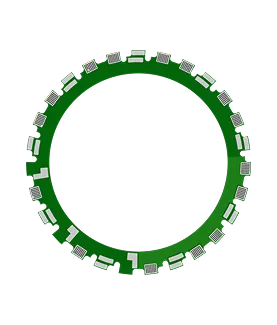
PCB Specifications
| Parameter | Value | Parameter | Value |
|---|---|---|---|
| PCB Type | FR4 PCB | Quantity | 100 pcs |
| Layers | 4 Layers | Board Type | Single PCB |
| Dimensions | 115 x 115 mm | Copper Weight | 6oz |
| Thickness | 2.5 mm | Min Track / Spacing | 6/6mil↑ |
| Surface Finish | HASL Lead Free | Min Hole Size | 0.3mm↑ |
| Solder Mask | Green | Silkscreen | White |
| Stack-up | Custom | Impedance Control | No |
Manufacturing Timeline
Logistics Information
Key Manufacturing Processes
Manufacturing Summary
This 4-layer FR-4 motor stator PCB (115 × 115 mm, 2.5 mm finished thickness, 6 oz copper on both inner and outer layers, TG150) was produced in a 100-piece run using lead-free HASL surface finish. The design featured a minimum 0.3 mm hole size and 6 mil trace/space geometry, with standard mechanical routing and no impedance requirements. Production used 100% flying probe testing and incorporated customer-specified stackup and material (FR-4 KB-6165F equivalent). The heavy copper weight and board thickness demanded careful attention to etching uniformity, registration, and thermal management throughout lamination and patterning.
During CAM review and DFM, several issues required resolution. The 0.35 mm holes were too small for reliable production pinning, so three additional 2.0 mm non-plated locating holes were added after confirmation. Multiple pads sat too close to the board edge, creating risk of copper exposure during milling; clearances were adjusted accordingly. Inconsistencies appeared between the provided Gerber data, silkscreen polarity (top negative with characters, bottom negative only), hole windowing (top/bottom open vs. bottom tenting per notes), and surface finish specifications. These were clarified and aligned with the engineering files before tooling release edge clearance and small-hole positioning controls followed established heavy-copper PCB manufacturing practices to maintain dimensional stability and avoid plating or routing defects.
All modifications were documented and verified prior to production. The order completed within the 18-day delivery window with full electrical testing and quality reports. Final boards met copper thickness, hole registration, and surface finish requirements, supporting reliable motor stator assembly performance.
Explore More PCB Manufacturing Resources
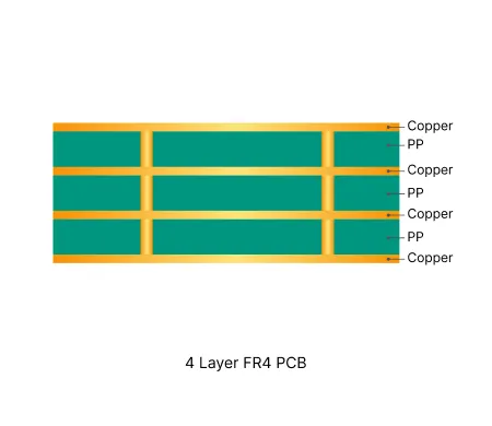
4 Layer FR4 PCB Manufacturing Insights
Standard multilayer solution offering practical routing density and controlled impedance for industrial and consumer electronics.
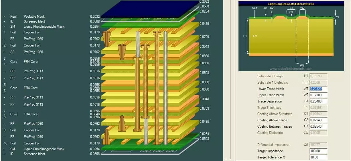
Multilayer FR4 PCB Engineering Queries Explained: Causes, Risks and Solutions
In-depth guide to the most frequent Engineering Queries (EQ) and DFM issues in Multilayer FR4 PCB (4/6/8+ layers) production. Real factory insights on stack-up confirmation, impedance control, copper balance, inner layer design, via treatment, registration, and practical prevention strategies.
Real Production Records
| Order ID | PCB Type | Layers | Dimensions | Solder Mask | Surface Finish | Quantity | Action |
|---|---|---|---|---|---|---|---|
| FR4-20260911-001 | FR4 PCB | 4 | 76.33 x 49.91 | Green | HASL Lead Free | 10 | View detail |
| FR4-20260910-004 | FR4 PCB | 2 | 69.92 x 69.91 | White | HASL Lead Free | 5 | View detail |
| FR4-20260907-001 | FR4 PCB | 2 | 90 x 40 | Green | HASL Lead Free | 30 | View detail |


