











PCB Specifications
| Parameter | Value | Parameter | Value |
|---|---|---|---|
| PCB Type | FR4 PCB | Quantity | 100 pcs |
| Layers | 10 Layers | Board Type | Single PCB |
| Dimensions | 37.15 x 31.3 mm | Copper Weight | 1oz |
| Thickness | 1 mm | Min Track / Spacing | 10/10mil |
| Surface Finish | ENIG (Immersion Gold) | Min Hole Size | 0.5mm |
| Solder Mask | Green | Silkscreen | White |
| Stack-up | Custom | Impedance Control | No |
Manufacturing Timeline
Logistics Information
Key Manufacturing Processes
Manufacturing Summary
We manufactured 100 pieces of these compact 10-layer FR4 circuit boards in single-board format, each measuring 37.15 × 31.3 mm and finished to 1.0 mm thickness. The custom stackup employed 1 oz copper on all layers with 10/10 mil minimum track and spacing. Green soldermask, white silkscreen, and immersion gold ENIG surface finish were applied according to specification. The absence of blind vias and impedance control allowed standard multilayer processing while directing attention to registration accuracy within the constrained board thickness.
Engineering review confirmed the stackup details prior to PCB material preparation and inner layer imaging. Precise layer stack alignment preceded high pressure lamination, ensuring reliable interlayer connections across all ten layers. Solder mask application was followed by electroless nickel deposition and immersion gold deposition to produce a flat, corrosion-resistant surface. Final electrical testing verified net continuity and isolation on every board produced.
Production was completed in 14.1 days with stable parameters maintained throughout the run. The batch exhibited consistent quality, delivering multilayer boards that fully conformed to the specified dimensions, copper weights, and ENIG finish requirements.
Explore More PCB Manufacturing Resources
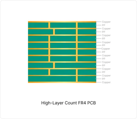
High-Layer Count FR4 PCB Manufacturing
These high-layer count FR4 PCB enable high-density interconnects while maintaining signal integrity and thermal reliability in computing and communication equipment.
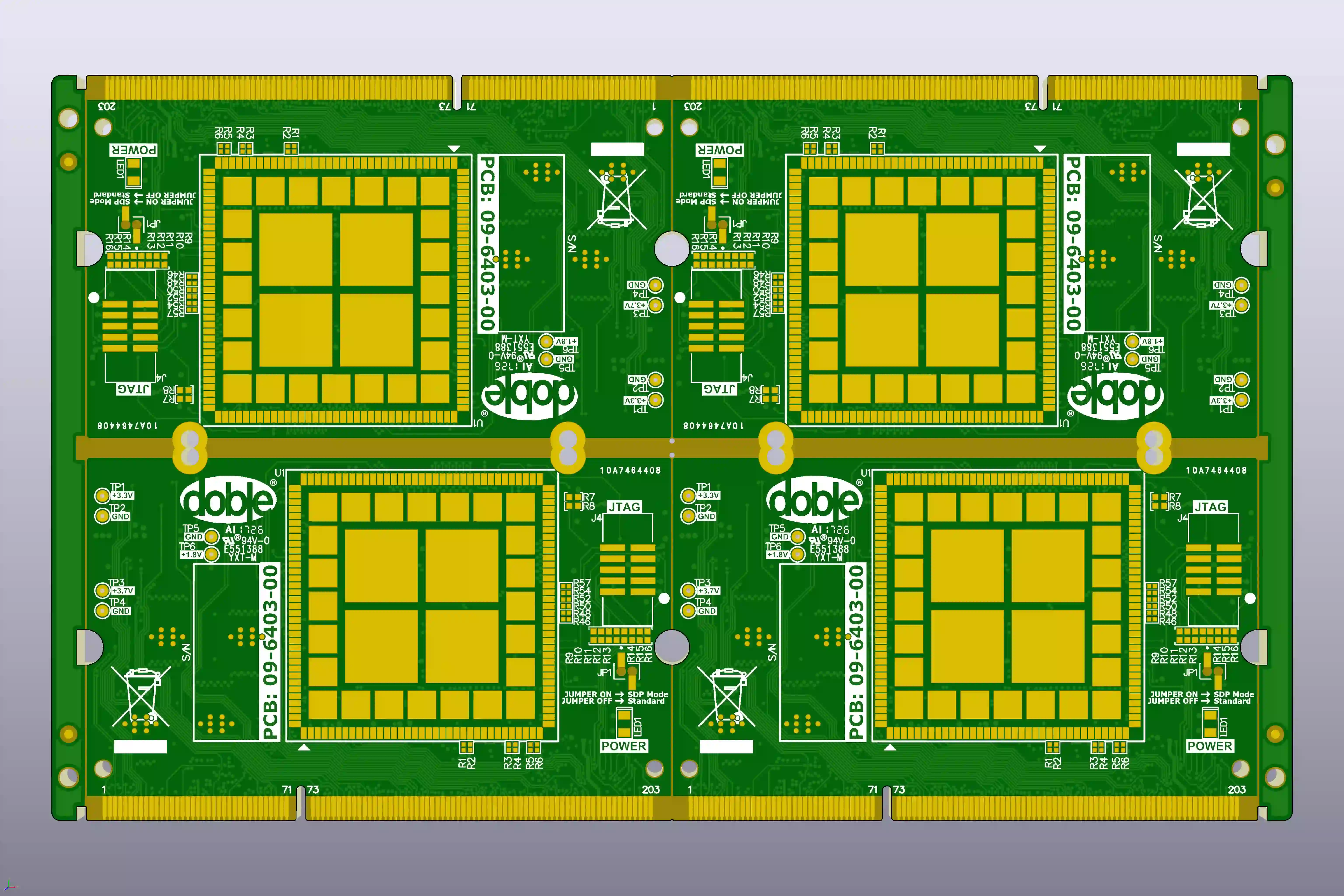
How to Resolve Gold Finger Bevel and Impedance EQs in 10-Layer PCBs
Real 10-layer FR-4 case study: how CAM engineers resolved gold finger bevel clearance, impedance mismatch, tight via spacing and plugging risks to prevent scrap and signal integrity failures.
Real Production Records
| Order ID | PCB Type | Layers | Dimensions | Solder Mask | Surface Finish | Quantity | Action |
|---|---|---|---|---|---|---|---|
| FR4-20260918-033 | FR4 PCB | 6 | 55 x 41.7 | Green | ENIG (Immersion Gold) | 5 | View detail |
| FR4-20260912-059 | FR4 PCB | 2 | 275 x 193.7 | Green | ENIG (Immersion Gold) | 100 | View detail |
| FR4-20260819-043 | FR4 PCB | 10 | 157 x 140 | Blue | ENIG (Immersion Gold) | 100 | View detail |


