LED display control systems rely on specialized PCBs that integrate high-speed data interfaces, precise power delivery networks, and robust signal routing to drive thousands of LEDs reliably. Whether for indoor signage, outdoor video walls, or dynamic advertising boards, every aspect of the control card—from connector placement to multilayer stack-up—directly impacts refresh rates, color accuracy, and long-term operational stability. Aivon’s PCB manufacturing expertise ensures these boards meet the demanding electrical, thermal, and mechanical requirements of modern LED installations.
Control System Architecture and PCB Integration
LED display control systems divide into asynchronous (offline) and synchronous architectures, each imposing distinct PCB constraints. Asynchronous cards store content locally and loop playback, favoring compact single- or dual-layer boards with integrated memory and simple RS232/485 or USB interfaces. Synchronous systems, used for real-time video, employ a sending card, multiple receiving cards, and DVI input, requiring multilayer PCBs with dedicated high-speed differential pairs and low-impedance power planes.
Advanced array-based architectures place a master control board, slave boards, and scan boards inside each cabinet. This distributed approach improves reliability by shortening trace lengths between controller and LED modules, reducing signal degradation. PCB designers optimize these systems with controlled-impedance routing, extensive via stitching for ground return paths, and separate analog/digital domains to prevent crosstalk during high-frame-rate operation exceeding 120 Hz.

Interface Standards and Connector Layout on Control PCBs
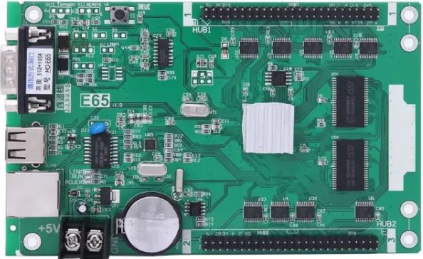
Common module interfaces dictate precise connector footprints and routing rules on the control card PCB. The yellow T08 interface suits indoor F3.75 or F5.0 modules, while the black T12 handles P10 single- or dual-color boards. The blue T75 (and newer 320-pin variants for fine-pitch) supports full-color modules. Proper LED PCB layout places these connectors with minimal stub lengths, matched trace impedances, and adjacent ground planes to maintain signal integrity across the 75-pin or 320-pin arrays.
Manufacturers and others standardize these pinouts, allowing Aivon to produce control cards with repeatable high-density interconnects. During fabrication, precise drilling and plating ensure reliable mating even after thousands of module insertions.
Calculating Sending and Receiving Cards: PCB Layout Implications
Determining the number of sending and receiving cards begins with module counts and pixel resolution, directly influencing PCB trace density and power distribution. For an indoor P10 display measuring 20 m × 10 m, 63 modules along each axis yield a 2016 × 1008 pixel resolution. With receiving cards rated at 256 × 128 pixels, eight cards per dimension produce a 64-card array, plus one spare. Sending cards rated at 1280 × 1024 pixels require two units to cover the full resolution.
Outdoor installations shift to cabinet-based calculations. A 20 m × 12 m P10 screen uses 273 cabinets of 960 × 960 pixels each. One receiving card per cabinet (government projects) or one per two cabinets (commercial) dictates the density of high-current power planes and connector arrays on the control PCB. These calculations guide stack-up decisions: thicker copper layers for power delivery and additional signal layers for the increased data lanes required by larger screens.
Power Distribution, Wiring Strategies, and Thermal Management on LED PCBs
Power integrity is critical when driving dense LED arrays. Straight-line (“I”) wiring of 220 V supplies creates excessive voltage drop and uneven current loading along long daisy-chained cables. For 30 supplies spaced 1 m apart, the first segment may carry 5.8 kW, risking overheating in undersized 1.5 mm² conductors. T-shaped wiring, with the feed entering at the midpoint, halves the maximum current per segment and allows safer 1.5 mm² cables while maintaining voltage above 200 V at the farthest supply.
On the PCB itself, these principles translate to wide copper pours, multiple parallel vias for high-current paths, and strategic placement of switching power supply connectors. Designers incorporate thermal vias and copper pours under power components to dissipate heat from 5 V / 5 A modules, preventing delamination in high-Tg FR4 or metal-core substrates. Brightness reduction further lowers thermal load, extending PCB and LED lifespan.
Control Card Types, Connectivity, and Update Methods
C-type, E-type, G-type, and F-type cards support varying scan modes (4/8/16) and pixel capacities up to 114,688 single-color pixels. USB and Ethernet variants reduce cabling complexity, while Wi-Fi, WeChat, and mobile interfaces add wireless modules that require careful PCB isolation to avoid RF interference with display data lines.
Text updates via USB, serial, Ethernet, or wireless methods all depend on clean signal paths from the control card to the modules. PCB layout must accommodate these interfaces with proper shielding, decoupling, and firmware-accessible test points for field debugging—especially important when troubleshooting power-related disconnections on 5 V Lingguan cards or pixel mismatches on 32 × 16 P10 modules.
Reliability, Debugging, and Manufacturing Considerations
Module tables (P3.75 to P10) and pitch-based pixel calculations guide final PCB routing density. Mismatches in expected dimensions frequently cause display artifacts, underscoring the need for precise registration during fabrication. Aivon’s controlled-impedance manufacturing, low-loss dielectrics, and rigorous in-circuit plus functional testing ensure every control card performs consistently across production batches.
By anchoring LED display control systems in disciplined PCB design—optimized interfaces, power planes, signal integrity, and thermal strategies—engineers achieve brighter, flicker-free, and longer-lasting installations. Whether calculating card quantities for a large video wall or selecting T-shaped power distribution for storefront signage, the underlying PCB remains the foundation of performance and reliability.