In production, factories control sheet metal bending tolerance by calculating expected springback upfront in the CAM or programming stage, then applying overbending compensation on the press brake while using consistent tooling and material batches to hold angles within ±1° and flange lengths to ±0.25–0.5 mm for standard operations.
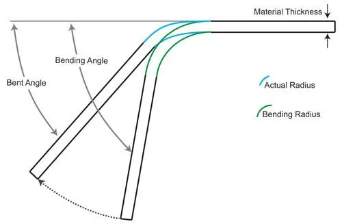
What we typically see on the shop floor is that material properties drive most of the variation right from the start. Sheet thickness can fluctuate within the supplier tolerance, grain direction affects how the metal flows, and yield strength varies slightly even within the same grade. These factors combine during bending to create predictable but unavoidable springback.
Springback Behavior Under Real Press Conditions
Springback appears because the outer fibers stretch while the inner ones compress, and upon release the elastic portion tries to return the material toward its original flat state. In production this shows up more with higher strength materials or larger bend radii relative to thickness. For mild steel around 1–3 mm thick we usually see 1–3° of springback on a 90° air bend, while stainless or high-tensile grades push it higher.
Operators notice it immediately when test bends come off the brake and don’t sit at the programmed angle. Thicker material tends to spring back less because the plastic zone dominates, but thin sheets amplify the effect due to lower stiffness.
Tooling and Mold Setup That Limits Deviation
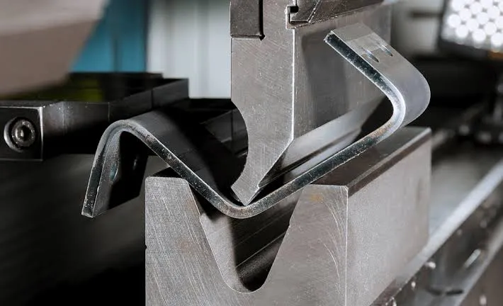
Mold selection directly influences how much the part moves after forming. Air bending is common for flexibility but offers less control over the final angle compared to bottoming or coining. In our setups we match V-die opening to material thickness—typically 6–8 times thickness for mild steel—to balance force and accuracy.
Worn punches or inconsistent die surfaces create additional variation, so production teams inspect and rotate tooling regularly. Consistent back gauge positioning is critical; any shift here multiplies across multiple bends and throws flange lengths out of tolerance.
Compensation Techniques Applied in Programming and Forming
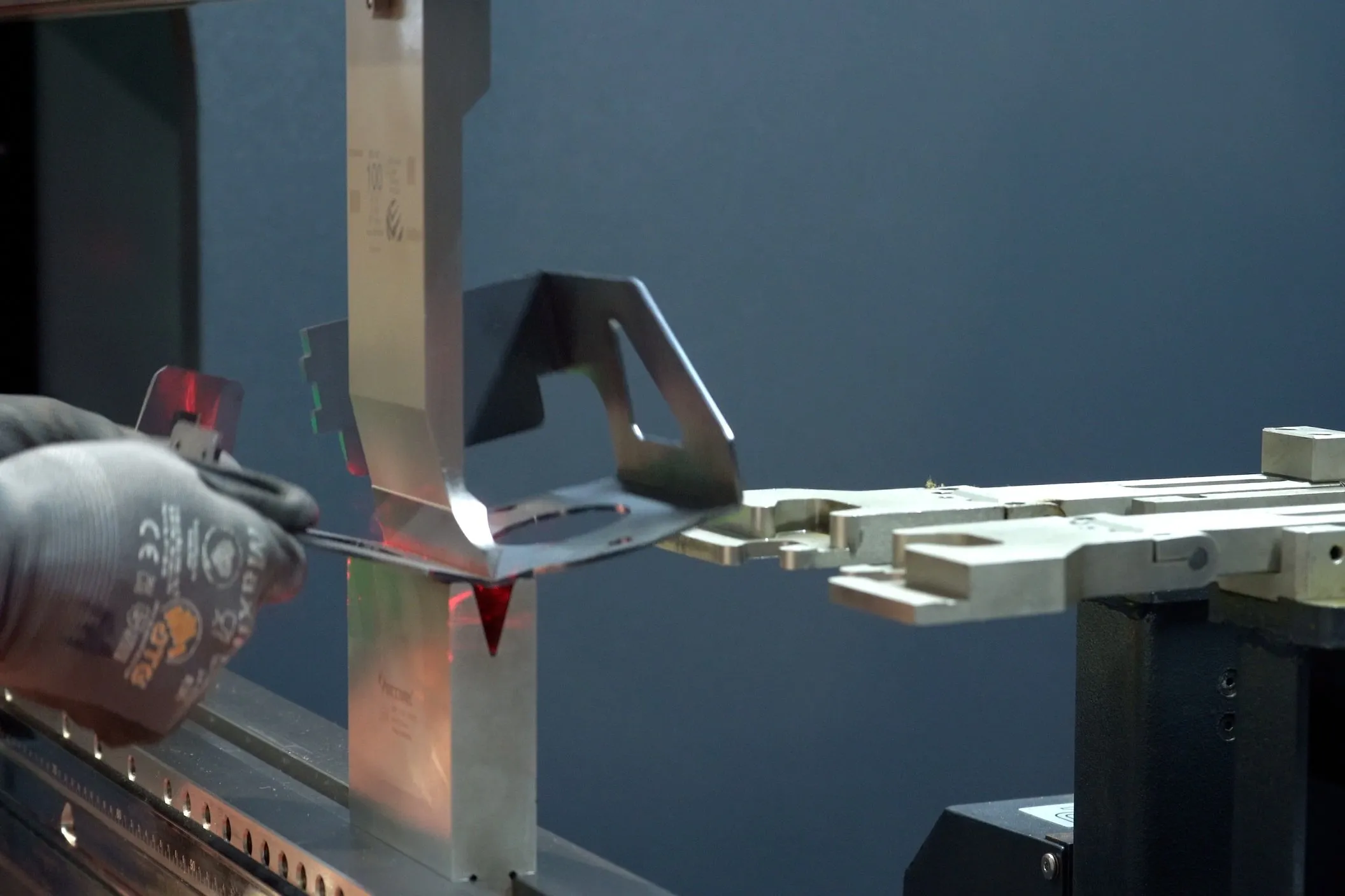
The main production approach is to overbend by the predicted springback amount. For a target 90° we might program 87–88° depending on the material data sheet and past runs. CNC press brakes store material-specific libraries so operators select the grade and thickness, and the control automatically applies the offset.
Bend allowance and deduction calculations in the flat pattern must use the actual K-factor for that batch rather than generic values. Factories often run a few test pieces, measure the actual springback, then update the program before full production. This iterative step keeps cumulative error low on parts with several bends.
Grain direction matters too. We try to keep bends perpendicular to the rolling direction where possible to minimize variation. When material comes from different coils we measure hardness or run quick bend tests to adjust compensation on the fly.
Inspection Methods That Catch Issues Early
After forming, parts go through first-article inspection using digital protractors, CMM arms, or dedicated angle gauges. We check both the bend angle and the resulting flange length against the drawing. For critical parts we use laser scanners or optical systems that capture the full geometry without contact.
In-line checks during a run involve pulling samples every 50–100 pieces depending on complexity. If angles start drifting, operators recalibrate the compensation or check for tool wear. This prevents large batches from going out of tolerance.
What Happens When Bending Tolerance Is Not Managed
Uncontrolled springback leads to parts that don’t mate correctly in assembly. Flanges end up short or long, holes misalign, and weld joints gap unevenly. This causes fit-up problems downstream, increased assembly time, or outright scrap when the part no longer fits the intended envelope.
In high-volume runs we have seen yield drop noticeably when material batches change without updated compensation. Rework becomes expensive because correcting formed parts often requires additional bending steps that risk cracking or work-hardening the material.
Practical Limits and When Looser Control Is Acceptable
Standard production tolerances for most commercial work sit around ±1° on angles and ±0.3–0.5 mm on linear dimensions after bending. Tighter requirements demand more time for test bends, higher-grade material consistency, or secondary operations like coining, which raises cost.
Exceptions are common on non-critical brackets or enclosures where the bend serves mainly for stiffness rather than precise fit. In those cases we can relax to ±2° and still meet functional needs. Designers help by clearly marking which dimensions are functional versus reference, allowing the shop to apply the right level of control.
From the fabrication side the key is communication early. Sending a clear DFM note about key features lets us plan the compensation strategy before cutting starts. This avoids surprises and keeps the job moving through the shop without extra iterations.
Overall, controlling sheet metal bending tolerance comes down to knowing the material, selecting appropriate tooling, applying data-driven compensation, and verifying at each stage. Production teams rely on experience with specific grades and machines more than theoretical formulas alone, because real coils and press conditions always introduce small differences that must be handled on the floor.
When these steps are followed consistently, parts come off repeatable enough for most assemblies without excessive cost or delay. Ignoring any link in the chain—material consistency, tooling condition, or inspection—quickly shows up as dimensional drift that affects the entire job.