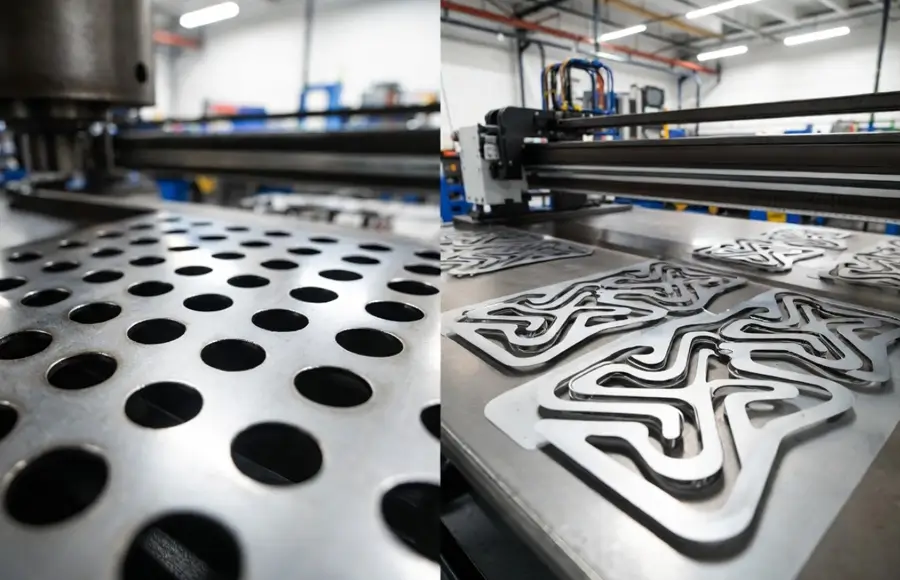
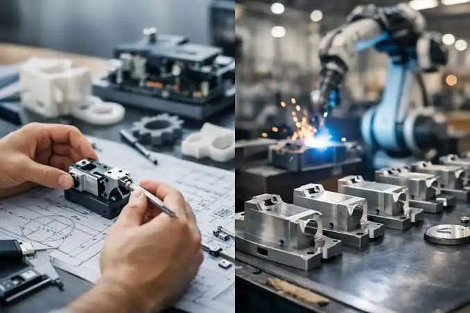
In production, we handle a sheet metal prototype by breaking it down into laser cutting for the flat pattern, press brake bending for the forms, welding or fastening for assembly points, surface treatment for protection and appearance, and final assembly with hardware or mating parts. CAM programmers generate the unfold from the 3D model, add bend allowances based on material and thickness, and nest parts on standard sheet stock to minimize waste while keeping tight tolerances on critical features.
How laser cutting sets the accuracy baseline for the entire run
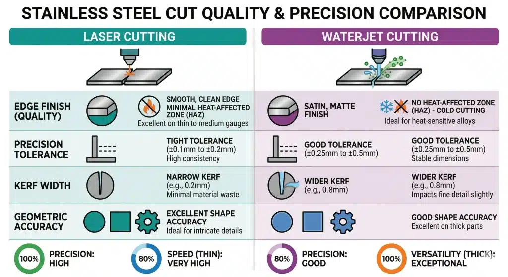
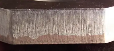
Laser cutting is usually the first real production step after we receive the files. We cut the developed flat pattern directly from the sheet using fiber laser for most materials up to 6mm thick. Kerf compensation gets applied automatically in the CAM software, typically 0.1-0.2mm depending on material and power settings. For sheet metal prototype work, we prioritize clean edges with minimal dross because any burrs will show up later during bending or welding.
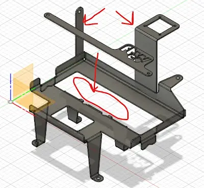
What we typically see on the shop floor is that designers sometimes forget to add proper hole-to-edge distances or tab reliefs. In production this shows up as distorted features or cracks at bend zones right after cutting. We flag these during DFM and suggest minimum 1.5x material thickness for hole margins on mild steel, more on stainless to avoid work hardening issues.
Material behavior right after cutting
Heat from the laser creates a small heat-affected zone. On thin aluminum or galvanized sheets this can cause slight warping if the nest is too dense. We adjust cutting order and use micro-tabs or skeleton support to keep parts stable until they come off the table. Ignoring this leads to parts that no longer match the flat pattern dimensions when they reach bending.
Why bending tolerances tighten up after the cut parts leave the laser
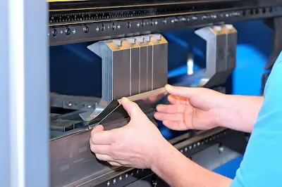
Bending comes next on the press brake. We use the unfold with accurate bend deduction or allowance calculated for the specific material, thickness, and tooling. For prototypes we often run air bending with standard V-dies rather than dedicated tooling to keep costs down. Springback compensation is critical — stainless steel bounces back more than mild steel, so we overbend by 1-3 degrees depending on the angle and grain direction.
From a fabrication standpoint this becomes sensitive because the laser-cut edges can have slight taper or burr that affects how the part sits in the die. If the bend lines were not properly relieved, material tears at the corners during forming. Most factories will handle this by adding standard relief cuts or adjusting notch geometry in CAM before sending to the floor.
Registration and sequence impact on final dimensions
Bending sequence matters a lot for complex parts. We bend from the inside out or follow the designer's callouts to avoid collision with already formed flanges. Cumulative tolerance stack-up is the real issue in prototypes — each bend can shift position by 0.2-0.5mm depending on material. This is why we measure after the first article and adjust the program for the rest of the small batch.
Welding challenges that appear when bent parts don't mate cleanly
Welding for sheet metal prototype is usually TIG or MIG depending on material and thickness. We tack first to check fit-up because gaps from bending variation will cause distortion or burn-through on thin stock. Fixtures are essential here — simple jig setups hold the parts in position while we weld. On prototypes we often leave extra material or adjust weld seams to accessible locations to reduce post-weld cleanup time.
What typically shifts is the overall geometry due to heat input. Thin sheets pull in toward the weld bead, throwing hole positions off. If ignored, the prototype won't assemble with mating components or pass functional checks. We control this by balancing welds, using clamping, and sometimes stress-relieving thin aluminum parts before final dimensions are locked.
Fit-up and distortion control in practice
CAM engineers add extra tabs or locator holes during flat pattern creation specifically for welding fixtures. In production this reduces setup time and improves repeatability across the handful of prototypes needed for validation.
Surface treatment timing and its effect on final dimensions
Surface treatment follows welding and deburring. Common options include powder coating, anodizing, zinc plating, or simple brushing and painting. We account for coating thickness in the design phase — powder coat can add 50-100 microns per side, which matters for tight fit tolerances. Parts get masked on critical mating surfaces or threaded holes before treatment.
From the factory side, doing surface finish too early risks damaging it during bending or welding. We usually complete all forming and joining first, then treat. This sequence avoids rework when the coating chips off at bend radii or weld zones.
Recommended Figure: Before and after surface treatment comparison on welded sheet metal prototype, highlighting powder coat coverage, masking areas, and thickness measurement points.
Final assembly and why small details determine prototype success
Assembly brings together the treated components with hardware, gaskets, or other sub-assemblies. We use the same fixtures from welding where possible to maintain alignment. For prototypes this step reveals any accumulated errors from earlier processes — misaligned holes, warped flanges, or coating interference.
In production we perform a full fit check and functional test before shipping. Adjustments at this stage are limited, which is why upstream DFM catches most issues. Threaded inserts, rivnuts, or spot welds get verified here for pull-out strength and location accuracy.
What happens when these steps are not tightly controlled
Skipping proper bend reliefs or laser kerf compensation leads to cracked corners and rejected parts. Poor fit-up in welding causes excessive grinding, distortion, and missed deadlines. Inconsistent surface prep results in coating adhesion failure during customer testing. Overall, yield drops fast on complex prototypes, turning a quick validation run into expensive scrap and redesign loops.
How factories actually compensate during a typical prototype job
We apply material-specific bend tables in the CAM system and run first article inspection with CMM or calipers on key features. Panel nesting maximizes material usage while leaving room for grain direction control. Welding sequences get documented on the traveler sheet. Tolerances are usually ±0.2mm on critical dimensions for prototypes, opening up for non-functional features. This keeps the process fast without sacrificing the data designers need for validation.
When we can relax certain controls on sheet metal prototypes
For very early visual models or non-structural parts we sometimes allow looser tolerances and skip full powder coat in favor of primer only. Simple brackets without tight mating features can use manual bending or fewer fixtures. Trade-off is reduced repeatability if the design later moves to higher volume. We always discuss these options during quoting so expectations match the prototype purpose.
Running a successful sheet metal prototype comes down to understanding how each process affects the next. Laser sets the foundation, bending introduces most variation, welding locks in the shape, surface treatment adds the finish, and assembly proves it all works together. Factories manage this daily by catching issues early in DFM and applying practical compensations at every step.