ptfe-pcbs
Polytetrafluoroethylene (PTFE) PCBs represent a specialized category of printed circuit boards engineered for demanding high-frequency and high-performance applications. These boards utilize PTFE as the primary substrate material, prized for its exceptional dielectric properties, including a low dielectric constant and minimal signal loss. This makes PTFE PCBs particularly suitable for industries such as telecommunications, aerospace, and radar systems, where maintaining signal integrity at gigahertz frequencies is critical. Engineers and designers often turn to this tag when seeking reliable solutions for environments involving extreme temperatures, moisture, or chemical exposure, as PTFE's inherent stability ensures long-term durability without compromising performance. Understanding the advantages of PTFE PCBs can guide better decision-making in circuit design. For instance, their low dissipation factor supports efficient power handling in RF amplifiers and antennas, reducing energy loss and heat buildup. Practical applications include microwave circuits, satellite communications, and medical imaging equipment, where precision and reliability are non-negotiable. Best practices involve selecting appropriate copper cladding and considering multilayer configurations to optimize impedance control, while accounting for PTFE's higher cost compared to standard FR-4 materials. By focusing on these aspects, users can achieve superior outcomes in projects requiring minimal electromagnetic interference. This tag compiles in-depth articles that delve into manufacturing techniques, material comparisons, and case studies on PTFE PCBs. Readers interested in enhancing their designs might find value in exploring topics like lamination processes or thermal management strategies, which provide actionable steps for implementation. Whether you are troubleshooting signal degradation or planning a new high-speed prototype, the resources here offer technical insights to support informed choices in electronics development.
Technical Articles
Troubleshooting Common Issues in PTFE PCB Assembly
Mastering Impedance Control in PTFE PCB Manufacturing: A Step by Step Guide
Exploring the Benefits of Multi Layer PTFE PCBs for Complex Designs
PCB RF Antenna Design and Layout: Engineering Principles, Isolation Techniques, and Manufacturing Integration
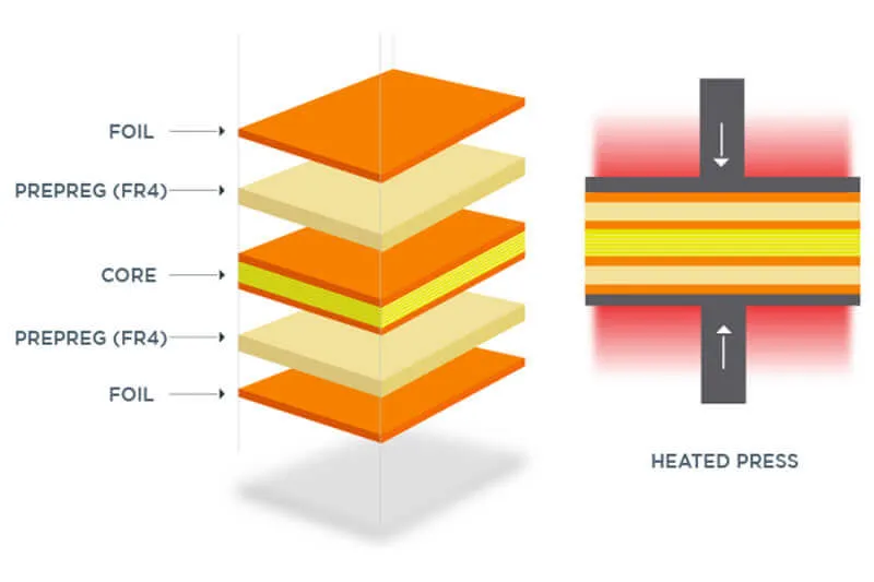
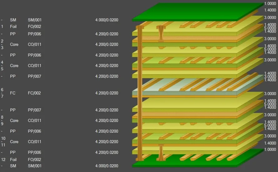
The Ultimate Guide to PTFE PCB Stackup Design for Optimal Performance
PTFE vs. FR 4: Choosing the Right PCB Material for Your Application
Unlocking High Frequency Performance: A Deep Dive into PTFE PCB Manufacturing
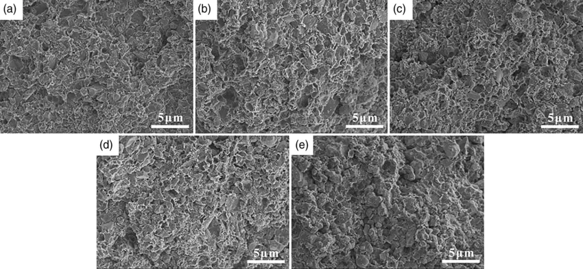
The Role of Fillers in RF Laminate PCB Materials: Enhancing Performance
Beyond FR 4: Exploring Advanced PCB Materials for High Performance LED Lighting
Beyond FR-4: Exploring Advanced PCB Materials for High-Frequency Applications
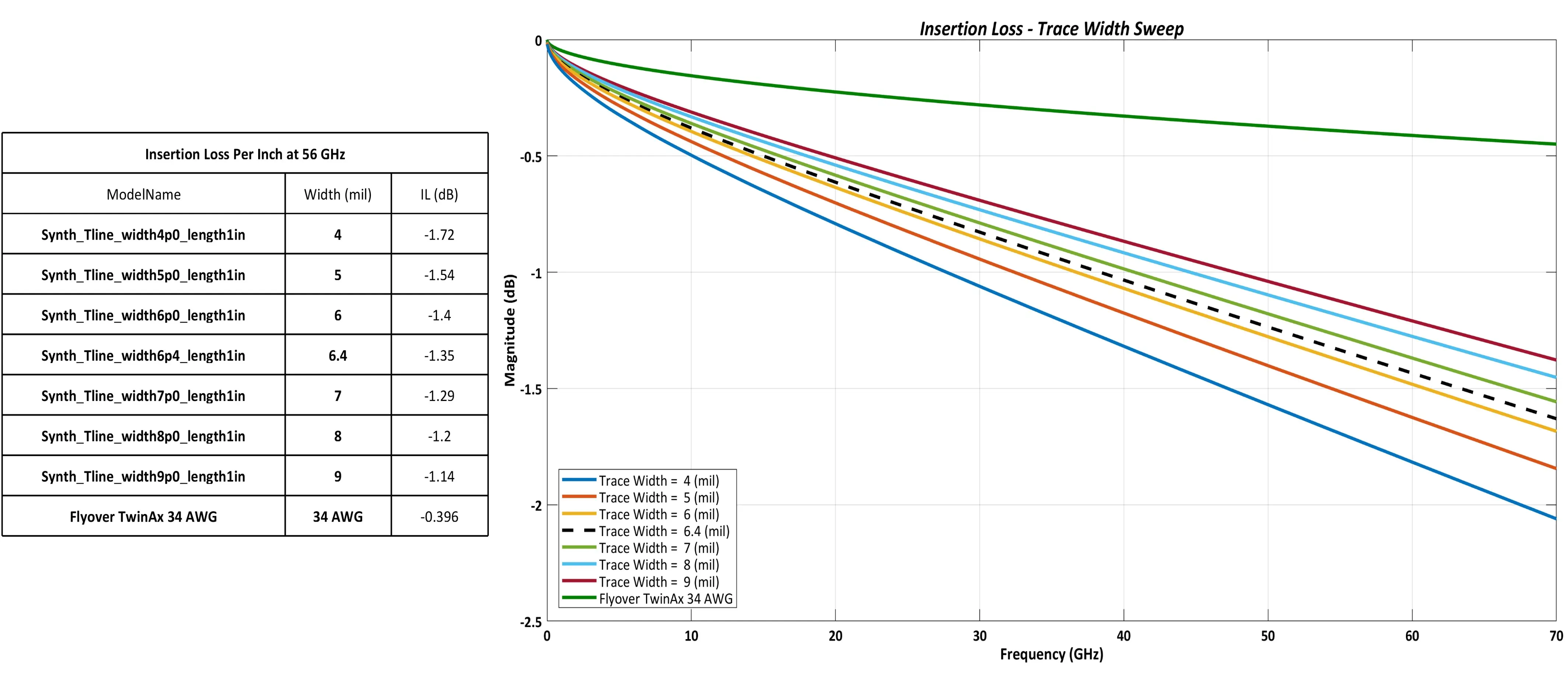
Signal Integrity Considerations for PTFE PCBs: Minimizing Loss and Maximizing Performance

Exploring the Material Properties of PTFE PCBs: Dielectric Constant, Loss Tangent, and Thermal Stability
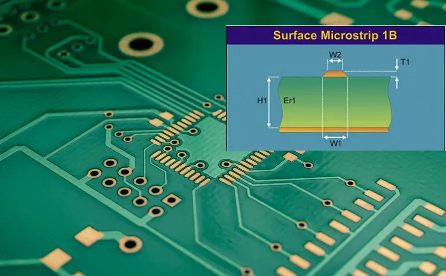
The Ultimate Guide to Designing PTFE PCBs for RF and Microwave Applications
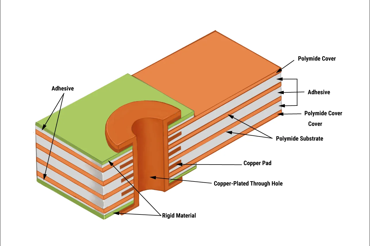
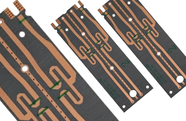
Beyond FR 4: Exploring Advanced Substrates for Rigid Flex PCB Assembly
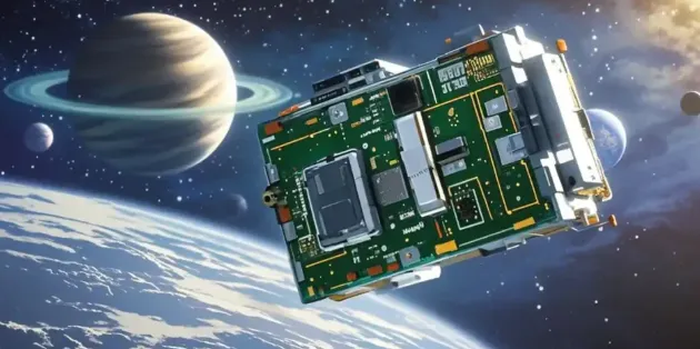
Selecting PCB Materials for Spacecraft: A Beginner's Guide
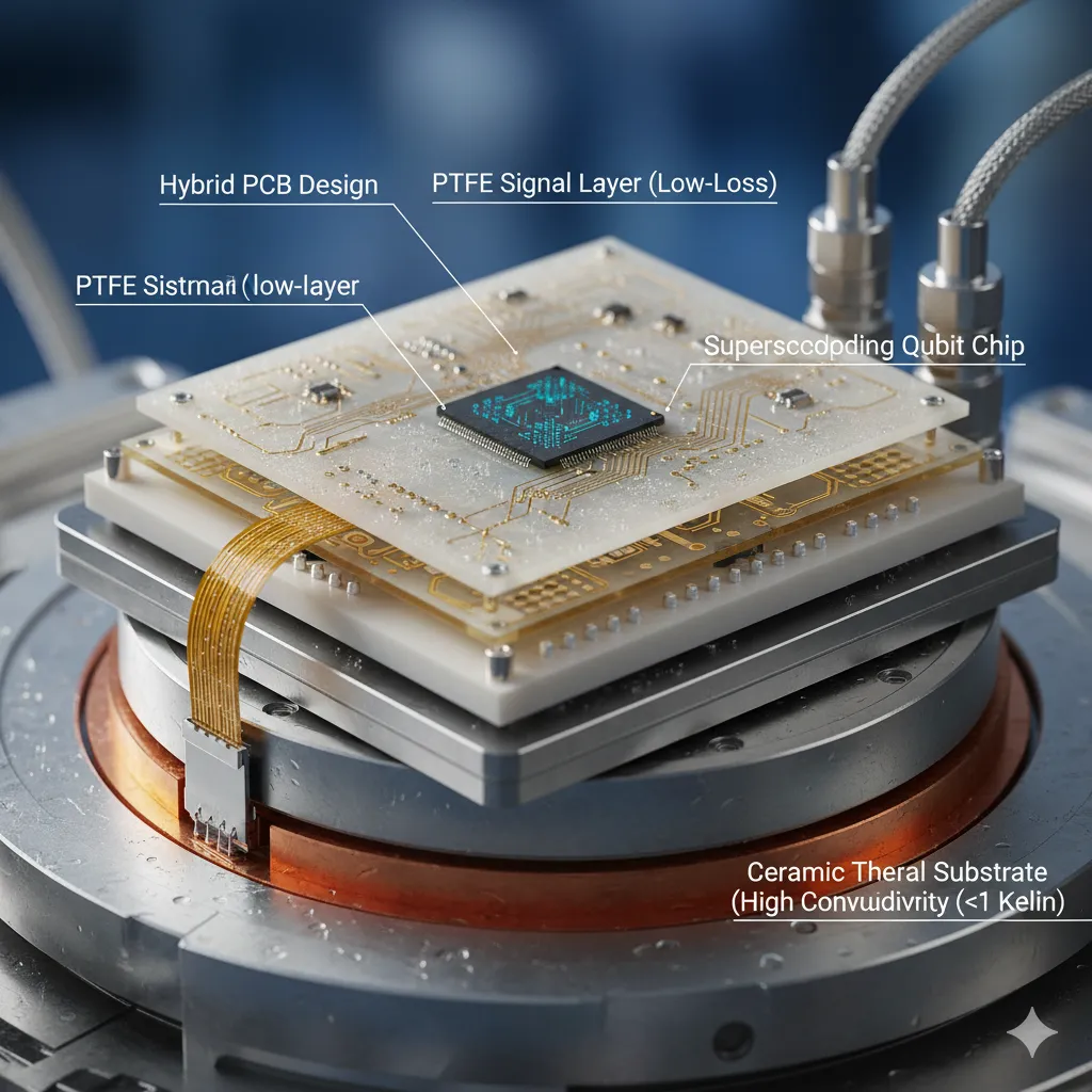
Advanced Materials for Quantum Computing PCBs: A Comprehensive Overview
Material Matters: Selecting the Best Laminates for High-Frequency Multilayer PCBs
Testing and Validation of PTFE PCBs: Ensuring Quality and Reliability
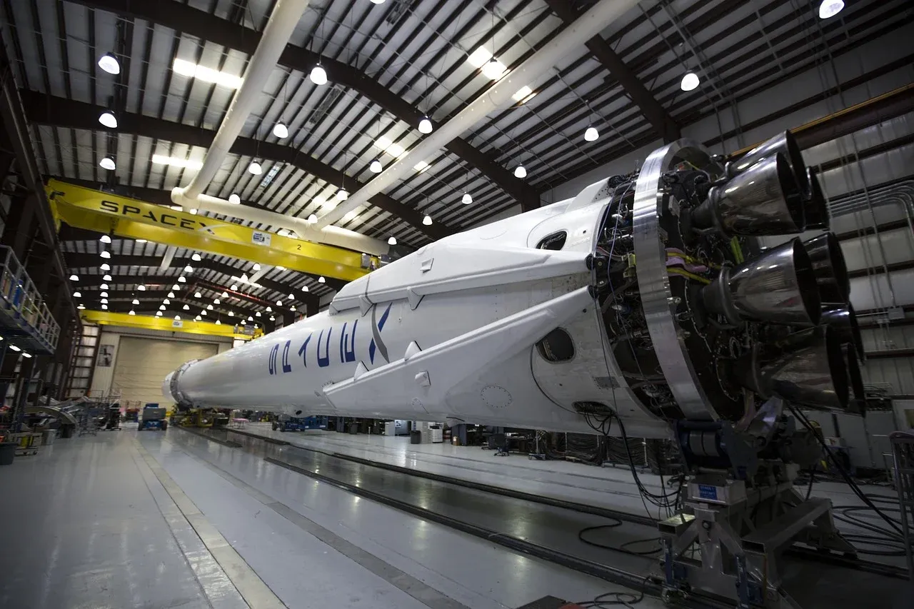
PTFE PCBs in Aerospace and Defense: Meeting the Demands of Extreme Environments
Get in Touch
Send Message
- Products & Service
- Company
- About AIVON
- Contact
- News
- Blog
- Certification
-


- Payment
-


2026 AIVON.COM All Rights Reserved