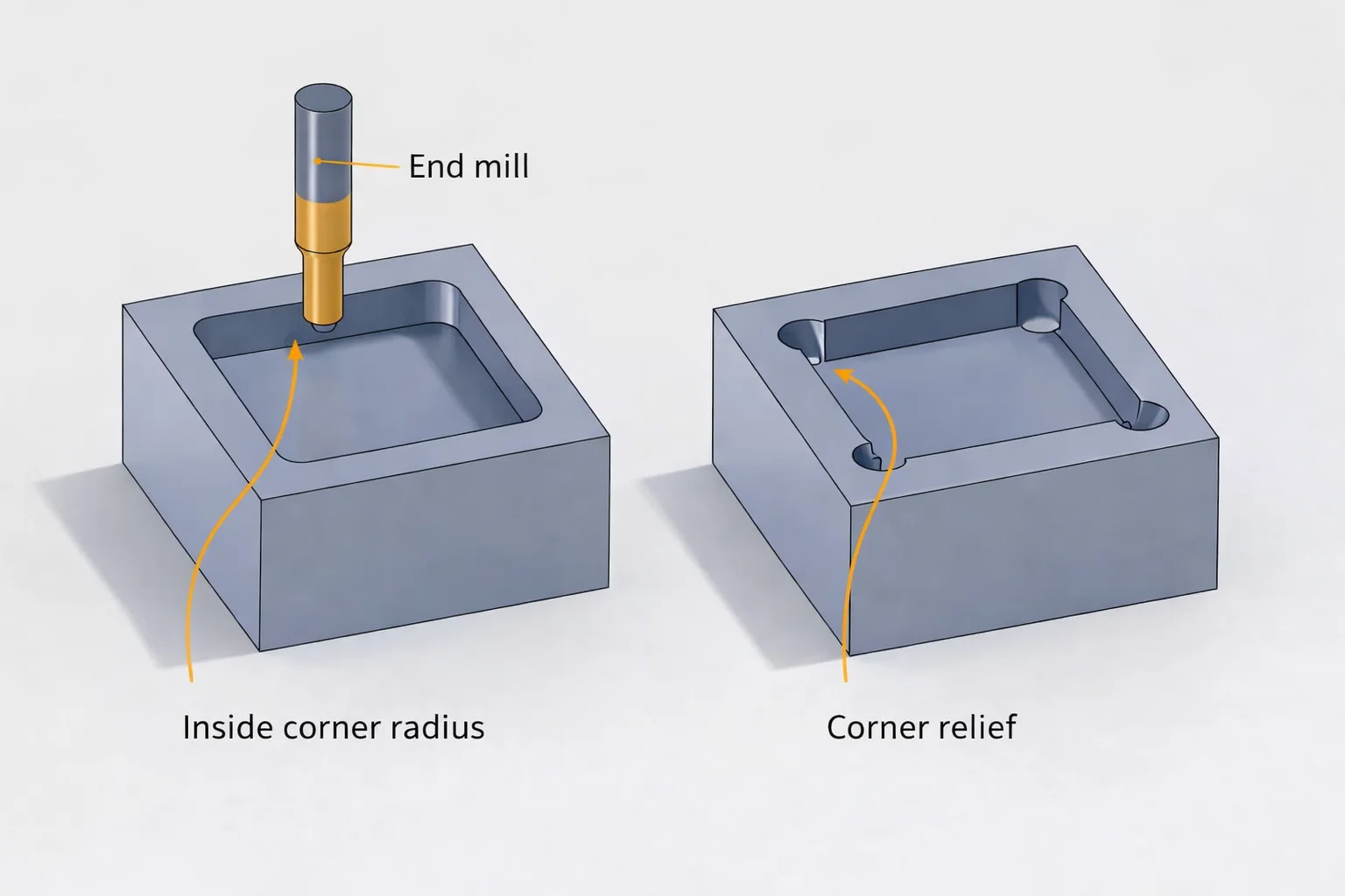
Sharp internal corners in CNC PCB enclosures look clean in the 3D model but create real headaches during fitting and assembly. The CNC end mill leaves a natural corner radius that rarely matches the zero-radius callout on the drawing.
This mismatch directly impacts how the PCB sits inside the enclosure and how components clear the walls. I've seen it force layout revisions multiple times.
Tool Limitations That Force CNC Enclosure Corner Radius
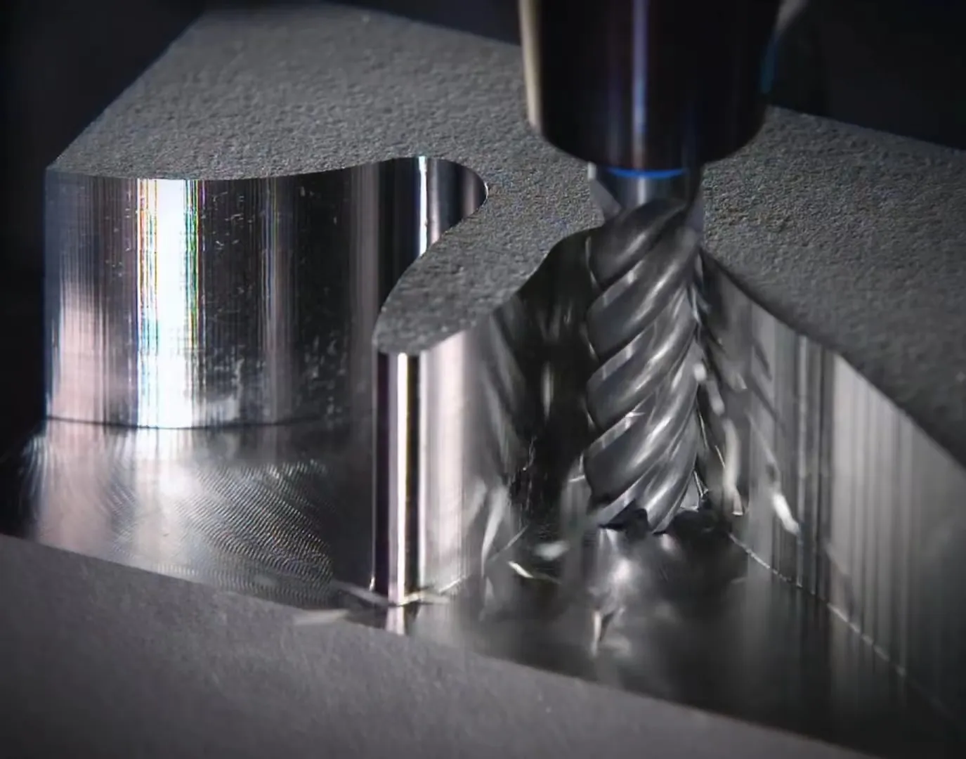
End mills have a finite diameter. The smallest practical tools for aluminum or plastic enclosures are usually 1mm to 2mm. That means every internal corner gets at least half that diameter as radius — typically 0.5mm to 1mm minimum.
Designers still draw sharp 90-degree corners in CAD expecting perfect machining. The shop either adds the radius themselves or the part comes back with broken tools and extra cost.
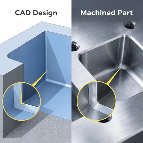
Smaller tools can reduce the radius but increase machining time dramatically and risk tool deflection or breakage in deeper pockets. Most production shops avoid them unless the job specifically calls for it and pays the premium.
How Missing CNC Enclosure Corner Radius Affects PCB Fit
The PCB outline gets designed to the sharp corner model. When the enclosure arrives with radii, the board either interferes at the corners or sits loose. Edge components end up closer to the wall than intended.
This is especially painful with castellated edges or boards that need to slide into slots. The radius eats into the available space, forcing the PCB inward or requiring manual filing on prototypes.
In tight enclosures the difference of 0.5mm per side adds up fast across multiple walls.
Why Layout Engineers Default to Sharp Corners
The mechanical model shows sharp corners. It looks precise. Copying that directly into the PCB keep-out or outline seems logical at the time. No one wants to guess the exact radius the shop will use.
Communication gaps between mech and PCB teams make it worse. The enclosure drawing might note "break all sharp edges" but never specifies the internal corner radius.
Structural and Assembly Risks from Corner Radius Mismatch
When the PCB is forced into a pocket designed for sharp corners, localized stress appears at the corners. This can crack the laminate or damage edge traces and vias.
During vibration or thermal cycling the board rocks slightly in the enclosure because it doesn't seat fully against the radiused corners. Mounting holes then see uneven loading.
Component clearance suffers too. Tall parts near the board edge end up closer to the enclosure wall than the 3D model predicted. Scraped components or shorting to metal walls become common failure modes.
Impact on PCB Layout Decisions Around Enclosure Features
The CNC enclosure corner radius forces changes in component placement near the board edges. Keep-out zones need extra margin — typically 0.75mm to 1.5mm beyond the nominal wall position depending on expected radius.
For boards that mount into recessed pockets, the outline itself should include the radius or at least generous fillets. Sharp PCB corners in radiused pockets create point contact that can chip the board or cause tilting.
Routing traces near the edge becomes riskier when the actual enclosure radius pushes the board position unpredictably.
Practical Radius Values That Work in Production
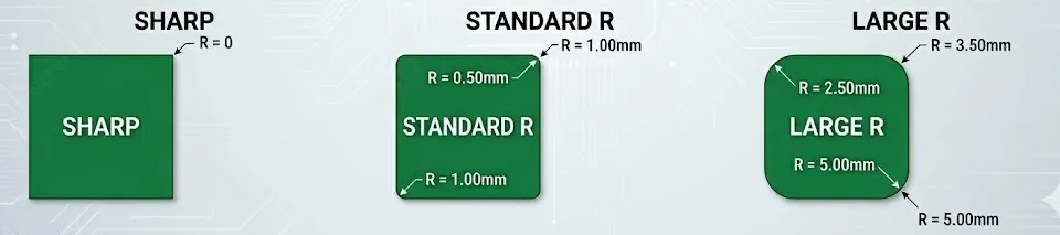
Specify 0.5mm minimum internal corner radius for most aluminum enclosures. 1mm is more common and cheaper for standard tooling. Call it out clearly on the drawing with a note that applies to all internal corners.
On the PCB side, add corresponding fillets to the board outline or increase the keep-out by half the expected radius plus tolerance. This prevents last-minute respins when the first articles don't fit.
Structural Optimization Around CNC Enclosure Corner Radius
Instead of fighting the radius, design with it. Use the natural fillet to strengthen the enclosure corners while giving the PCB more predictable fit. Some shops can add corner relief pockets but that adds operations.
For high volume, consider adjusting the enclosure boss positions or adding alignment features that don't rely on the exact corner geometry. The mounting holes still need to account for the overall shift caused by radii on multiple sides.
In deep pockets the tool reach and deflection make larger radii almost mandatory. Ignoring this leads to tapered walls or inconsistent dimensions that throw off the entire PCB fit.
DFM Adjustments That Prevent Corner-Related Issues
Always request the expected corner radius from the enclosure vendor before finalizing the PCB outline. Incorporate it into the 3D model for interference checking.
On dense boards, move critical components inward by at least 1mm from the nominal edge when working with CNC enclosures. Add teardrops or thicker traces near edges if routing must stay close.
For prototypes, consider laser-cut or 3D printed enclosures first to validate fit, but remember CNC production behaves differently due to the tool radius.
The key is treating CNC enclosure corner radius as a real manufacturing constraint rather than something to clean up later. It affects mechanical integrity, assembly yield, and long-term reliability more than most teams admit early in the project.
Engineering Takeaways for Future Designs
Sharp internal corners in CNC PCB enclosures are almost never worth the fight. Build the radius into both the mechanical and PCB designs from the start. It simplifies fitting, reduces stress concentrations, and avoids unnecessary iterations.
Check the tooling capability of your chosen enclosure vendor and document the CNC enclosure corner radius requirement clearly. Your layout will be more robust and the assembly team will have fewer surprises.
Small details like this separate designs that work smoothly in production from those that need constant tweaks.