










Introduction
Modern electronics demand higher power densities and faster signal speeds, which intensify thermal challenges in printed circuit boards. Rogers PCBs, fabricated with advanced laminates, excel in managing these issues due to their inherent material properties that support superior heat dissipation. Optimizing PCB design for better heat dissipation ensures efficient thermal management, directly enhancing PCB reliability in applications like RF systems, power electronics, and automotive modules. Engineers must prioritize thermal pathways during layout to prevent hotspots that degrade performance and lifespan. This article explores the principles and practices for leveraging Rogers PCB characteristics to achieve optimal thermal performance. By integrating structured design strategies, designers can mitigate risks associated with excessive temperatures.
What Are Rogers PCBs and Why Heat Dissipation Matters
Rogers PCBs refer to printed circuit boards constructed using specialized high-performance laminates that offer low dielectric loss, stable electrical properties, and enhanced thermal characteristics compared to standard FR4 materials. These laminates typically exhibit higher thermal conductivity and a coefficient of thermal expansion that closely matches copper, reducing mechanical stress during thermal cycling. Heat dissipation becomes critical in modern electronics because components such as power amplifiers and processors generate significant Joule heating, which can exceed safe operating limits if not properly managed. Poor thermal management leads to accelerated aging, electromigration in traces, and delamination at interfaces. For electric engineers, understanding these dynamics is essential for maintaining signal integrity and overall system reliability. In high-frequency and high-power environments, Rogers PCBs provide a foundation for designs that sustain performance under thermal stress.
The relevance of efficient thermal management extends to compliance with industry expectations for long-term PCB reliability. Excessive temperatures compromise solder joint integrity and material stability, potentially causing field failures. Rogers materials address this by facilitating better conduction paths for heat away from critical components. Designers focusing on heat dissipation optimization early in the process avoid costly iterations during prototyping. This approach aligns with the demands of compact devices where airflow is limited, making conduction the primary heat transfer mechanism.
Technical Principles of Heat Dissipation in Rogers PCBs
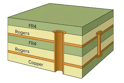
Heat dissipation in PCBs primarily occurs through conduction within the board structure, supplemented by convection to ambient air and minor radiation effects. The thermal conductivity of the laminate governs in-plane and through-plane heat spreading, with Rogers materials offering values that surpass those of epoxy-based alternatives, enabling more uniform temperature distribution. Engineers model heat flow using Fourier's law, where heat flux is proportional to the temperature gradient and material conductivity. Copper layers act as primary heat spreaders due to their high conductivity, while the core dielectric influences vertical heat transfer. Low CTE in Rogers laminates minimizes warpage and via cracking under thermal expansion mismatches, preserving thermal paths over repeated cycles.
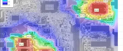
Trace heating follows principles outlined in IPC-2152, which provides guidelines for current-carrying capacity based on temperature rise, board thickness, and copper cross-section. Wider traces or increased copper thickness reduce resistance and associated I2R losses, but designers must balance this with signal integrity requirements. Multilayer stackups enhance dissipation by embedding power and ground planes that form thermal capacitors, storing and redistributing heat. Vias filled with conductive epoxy or plated copper bridge layers, creating vertical conduits with minimal thermal resistance. Finite element analysis reveals hotspots, guiding iterative improvements in layout for Rogers PCBs.
Component junction temperatures drive the need for precise thermal modeling, incorporating package theta values and board-level impedances. Rogers PCBs benefit from their dimensional stability, which maintains via integrity and plane coupling even at elevated temperatures. Radiation contributes negligibly unless surfaces are polished, so focus remains on conductive enhancements. Understanding these mechanisms allows engineers to predict and verify performance before fabrication.
Best Practices for Optimizing PCB Design with Rogers Materials
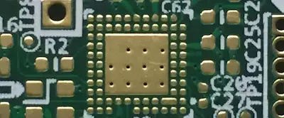
Start with material selection tailored to thermal demands, choosing Rogers laminates with optimized conductivity for the application's power density. Increase copper weight in outer layers to 2 oz or more for better spreading, while ensuring plating uniformity per IPC-2221 design guidelines. Place high-power components centrally or near board edges with direct paths to heatsinks, minimizing trace lengths to reduce voltage drops and heating. Thermal vias arrays under hotspots, spaced at 0.5 mm pitch with 0.2 mm diameter, improve through-plane conduction without compromising routability.
Incorporate embedded ground planes adjacent to signal layers to act as heat sinks, leveraging the low loss tangent of Rogers materials for dual electrical and thermal benefits. Effective rogers PCB design also utilizes blind or buried vias to shorten thermal paths in high-layer-count boards, avoiding unnecessary through-vias that add capacitance. Simulate stackups to optimize core and prepreg thicknesses, ensuring symmetric builds that prevent bow and twist. For efficient thermal management, integrate cutouts or slots in non-critical areas to enhance convection, particularly in natural airflow scenarios.
Component mounting strategies include direct die attach or thermal pads with high filler content for interface conductivity. Follow JEDEC guidelines for board-level thermal characterization to validate designs against real-world conditions. Post-layout checks for delta-T across the board should target less than 20°C variation. These practices collectively boost PCB reliability by distributing heat evenly.
Troubleshooting Common Thermal Issues in Rogers PCB Designs
Engineers often encounter uneven heating due to asymmetric stackups, leading to localized hotspots near edge-mounted components. Verify symmetry and add balancing copper pours to equalize CTE effects. Via barrel cracking from thermal cycling signals inadequate plating thickness; increase to 25 microns and use filled vias for high-stress areas. Delamination risks arise from moisture entrapment, so bake boards pre-assembly and control ramp rates during reflow.
Over-reliance on simulation without validation causes discrepancies; perform infrared thermography on prototypes to correlate models. Excessive trace temperatures indicate undersized conductors, addressed by IPC-2152 charts adjusted for external airflow. Power plane voids from lamination defects disrupt spreading; inspect via X-ray and refine press cycles. Systematic troubleshooting maintains the advantages of Rogers PCBs in demanding environments.
Conclusion
Rogers PCBs enable superior heat dissipation through material advantages and design optimization, critical for reliable modern electronics. Key principles like conduction dominance and low CTE guide effective layouts, while best practices such as thermal vias and heavy copper ensure performance. Adhering to standards like IPC-2152 and IPC-2221 provides a structured path to efficient thermal management. Engineers implementing these strategies achieve balanced designs that withstand thermal stresses. Prioritizing PCB reliability from concept to production yields robust systems ready for high-power applications.
FAQs
Q1: What advantages do Rogers PCBs offer for heat dissipation in high-power designs?
A1: Rogers PCBs feature higher thermal conductivity and matched CTE to copper, facilitating efficient heat spreading compared to FR4. This reduces junction temperatures and enhances PCB reliability under load. Optimizing PCB design with these materials involves thermal vias and plane utilization for uniform dissipation. Engineers benefit from lower risk of electromigration and warpage in RF and power applications.
Q2: How does IPC-2152 guide trace sizing for better heat dissipation?
A2: IPC-2152 provides data on temperature rise versus current, board parameters, and copper thickness for accurate trace width calculations. It supersedes older charts, accounting for multilayer effects and airflow. For Rogers PCBs, apply these to minimize I2R heating while preserving signal integrity. This standard ensures safe operation, supporting efficient thermal management.
Q3: What role do thermal vias play in optimizing PCB design for Rogers materials?
A3: Thermal vias create low-resistance paths through the stackup, channeling heat from components to inner planes or opposite surfaces. Array them densely under hotspots with plated or filled barrels to maximize conductivity. In Rogers PCBs, their stability under cycling preserves performance. Combine with ground planes for comprehensive heat dissipation.
Q4: Why is efficient thermal management essential for PCB reliability?
A4: Efficient thermal management prevents degradation from hotspots, such as solder fatigue and dielectric breakdown. Rogers PCBs amplify this by enabling conduction-focused designs. Monitor delta-T and validate with testing to meet reliability targets. This sustains long-term performance in compact, high-density electronics.
References
IPC-2152 — Standard for Determining Current Carrying Capacity in Printed Board Design. IPC.
IPC-2221 — Generic Standard on Printed Board Design. IPC.
JEDEC JESD51 — Methodology for the Thermal Measurement of Component Packages. JEDEC.






