Introduction
Virtual reality headsets represent a pinnacle of compact electronics engineering, where every gram and millimeter counts toward user comfort and immersion. Traditional rigid printed circuit boards struggle to conform to the ergonomic curves of head-mounted displays, leading to bulkier designs and added weight. Flexible printed circuits, or flex PCBs, address these limitations by enabling circuits that bend and twist to match the headset's form factor. In flexible PCB applications, these boards interconnect sensors, displays, processors, and batteries across dynamic surfaces. This approach not only lightens the overall assembly but also enhances reliability in motion-intensive environments. Engineers designing lightweight VR headset designs increasingly turn to flex PCBs for their adaptability and performance.
What Are Flex PCBs and Why Do They Matter in VR Headset Design?
Flex PCBs consist of conductive traces etched onto a flexible substrate, typically polyimide film, which allows repeated bending without failure. Unlike rigid boards made from fiberglass-reinforced epoxy, flex circuits eliminate the need for bulky connectors and wiring harnesses. In VR headsets, where space constraints demand integration into curved housings and adjustable straps, flexible circuit boards VR provide seamless electrical pathways. They support single-sided, double-sided, or multilayer configurations, often combined with rigid sections in rigid-flex hybrids for component mounting. The relevance stems from VR's requirements for high-density interconnects amid user head movements, vibrations, and thermal cycling. Bendable PCB VR solutions reduce assembly complexity, cutting weight by integrating functions that rigid alternatives cannot achieve without added mechanical supports.

Technical Principles Behind Flex PCBs in VR Applications
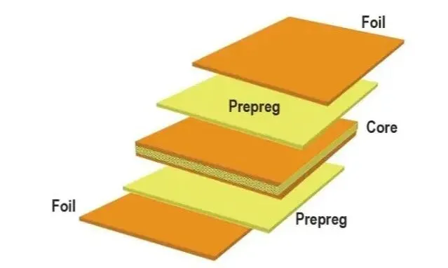
The core mechanism of flex PCBs relies on the ductility of thin copper foils laminated to flexible dielectrics, enabling controlled deformation. Polyimide substrates offer superior thermal stability and tensile strength compared to polyester alternatives, maintaining integrity across wide temperature ranges encountered in VR processors and displays. Design principles dictate that bend areas feature parallel traces with generous spacing to prevent cracking under strain, while rigid zones accommodate surface-mount devices. Signal propagation in high-speed VR interfaces, such as those for 4K displays or IMU sensors, demands precise impedance control through stackup optimization and ground planes. Thermal management involves low thermal expansion mismatch between layers to avoid delamination during operation. Adhesion between copper and substrate, tested via peel strength methods, ensures long-term reliability in dynamic VR environments.
Multilayer flex PCBs extend this by incorporating blind vias and filled structures for density, but require careful plating to withstand flexing. The minimum bend radius scales with conductor thickness and layer count, guiding engineers to simulate stress via finite element analysis during layout. Electromagnetic interference shielding via embedded ground layers protects sensitive VR signals from crosstalk in compact volumes. Vibration resistance comes from the boards' inherent compliance, absorbing shocks better than rigid counterparts. Fabrication involves sequential lamination and laser drilling for precision, aligning with performance classes defined in IPC-6013E. These principles collectively enable VR headset flex PCB to deliver uncompromised functionality in form factors under 200 grams.

Flex PCB Advantages in VR Headset Design
One primary flex PCB advantage VR offers is substantial weight reduction, as thinner substrates and eliminated connectors shave ounces from headsets already hovering near user tolerance limits. This directly translates to longer wear sessions without fatigue, critical for immersive experiences. Flexible circuit board VR designs also minimize volume by routing signals along contours, freeing space for optics and batteries. Reliability improves in moving assemblies, like adjustable head straps or folding mechanisms, where rigid boards would fracture at hinges. Assembly yields rise due to fewer interconnections, reducing points of failure in high-volume production. Cost efficiencies emerge over time through simplified tooling and testing compared to custom harnesses.
Another key benefit lies in enhanced thermal dissipation; flex materials conduct heat away from hotspots more uniformly than rigid laminates. In VR, where GPUs and OLEDs generate localized warmth, this prevents hotspots that degrade performance. Bendable PCB VR withstands millions of flex cycles, suiting daily use in gaming or training applications. Integration with sensors distributed across the headset frame becomes straightforward, supporting 6DoF tracking without wiring tangles. Scalability to rigid-flex hybrids allows mounting of ball grid arrays on stable sections while flex tails connect peripherals. Overall, these advantages position flex PCBs as essential for next-generation lightweight VR headset design.
Best Practices for Designing VR Headset Flex PCBs
Start with stackup definition early, specifying flex and rigid regions to balance mechanical needs with electrical performance. Use design rules that enforce no vias or pads in constant-flex zones, opting for flying leads or edge connectors instead. Incorporate stiffeners, such as polyimide or FR4 frames, under component areas to prevent warping during soldering. Trace routing in bend areas should follow annular rings and teardrops for strain relief, with wider lines for power distribution. Simulate dynamic stresses using tools compliant with IPC-2223E guidelines to predict fatigue life.
Material selection prioritizes low-dielectric-constant polyimides for high-frequency VR signals, ensuring minimal loss up to millimeter-wave bands if needed. Coverlays protect traces while allowing access for terminations, with registration tolerances held tight for multilayer alignment. During prototyping, validate bend performance through cyclic testing, monitoring resistance changes and visual cracks. For assembly, follow class 3 guidelines to handle fine-pitch components on rigid islands. Documentation should include bend axis orientations and handling instructions to prevent damage pre-installation. These practices ensure VR headset flex PCB deliver robust, field-proven performance.

Challenges in Flex PCB Implementation for VR and Engineering Solutions
Flex fatigue from repeated bending poses a primary challenge, exacerbated by VR's motion profiles; engineers mitigate this by defining flex limits and using annealed copper for ductility. Manufacturing tolerances for thin dielectrics demand precise etching, where over-etching leads to opens in fine traces. Solution involves statistical process control and in-line metrology during production. Thermal expansion differences in multilayer stacks can cause delamination; select matched CTE materials and validate via thermal cycling per IPC-6013E qualification.
Signal integrity degrades with flex-induced micro-cracks, addressed by redundant routing or shielding meshes. Component attachment on flex requires low-stress adhesives to avoid peel-off under vibration. Cost escalates for high-layer counts, so optimize by hybridizing with rigid sections only where necessary. Testing protocols include bend radius verification and environmental exposure to simulate headset lifecycles. Troubleshooting often reveals issues at transitions; reinforce with strain-relief features. By anticipating these, designs achieve high reliability in demanding VR applications.
Conclusion
Flex PCBs unlock transformative possibilities in VR headset design, blending mechanical flexibility with electrical precision for unparalleled lightness and integration. Engineers leverage their advantages in weight savings, space efficiency, and durability to push immersion boundaries. Adhering to structured principles and best practices ensures compliance with rigorous demands. As VR evolves toward untethered, all-day wearables, bendable PCB VR will remain central. Prioritizing these technologies positions designs for future-proof performance and user satisfaction.
FAQs
Q1: What are the main flex PCB advantages VR headsets gain?
Flex PCB advantages VR include drastic weight reduction for comfortable extended wear, compact routing along curved surfaces, and superior vibration resistance during head movements. They eliminate bulky connectors, simplifying assembly and boosting reliability in dynamic environments. Compliance with standards like IPC-6013E ensures performance under thermal and mechanical stress, making them ideal for lightweight VR headset design.
Q2: How does a VR headset flex PCB improve lightweight VR headset design?
A VR headset flex PCB enables thinner, bendable interconnects that conform to ergonomic shapes, cutting overall mass compared to rigid boards. It supports distributed sensors and displays without harnesses, optimizing volume. Engineers achieve this through polyimide substrates and rigid-flex hybrids, enhancing balance and battery life. This directly addresses the need for sub-300-gram headsets in prolonged use.
Q3: What design considerations apply to flexible circuit board VR layouts?
For flexible circuit board VR, prioritize bend zones free of vias, with traces parallel to flex axis per IPC-2223E. Use stiffeners for components and simulate strain to predict cycles. Impedance control maintains signal quality for high-res displays. Validate with cyclic bending and thermal tests to ensure durability in headset motions.
Q4: Why choose bendable PCB VR over traditional rigid boards?
Bendable PCB VR offers adaptability to complex geometries, reducing weight and failure points in moving parts like straps and lenses. Rigid boards limit form factors, adding bulk; flex versions integrate seamlessly for better thermals and reliability. They support high-density features essential for immersive tracking and graphics, aligning with modern lightweight VR headset design goals.
References
IPC-6013E — Qualification and Performance Specification for Flexible/Rigid-Flexible Printed Boards. IPC
IPC-2223E — Sectional Design Standard for Flexible/Rigid-Flex Printed Boards. IPC
IPC-A-610H — Acceptability of Electronic Assemblies. IPC