Introduction
Greenhouse automation relies on precise monitoring and control of environmental factors to maximize plant growth and resource efficiency. Custom sensor printed circuit boards (PCBs) serve as the backbone for integrating temperature, humidity, light, CO2, and ventilation controls into a cohesive system. A greenhouse climate control PCB coordinates data from multiple sensors to enable real-time adjustments, preventing issues like overheating or excessive moisture buildup. Electric engineers designing these systems must consider PCB layout, signal integrity, and environmental resilience to ensure reliable performance in humid, variable conditions. This article explores the design principles, best practices, and integration strategies for key sensor PCBs used in greenhouse automation. By optimizing these components, engineers can achieve automated, energy-efficient climate management that supports sustainable agriculture.

The Importance of PCBs in Greenhouse Climate Control
Greenhouses face unique challenges from fluctuating temperatures, high humidity levels, and varying light exposure, all of which impact crop yields. A well-designed greenhouse climate control PCB integrates sensors and actuators to maintain optimal conditions, reducing manual intervention and energy waste. These PCBs process analog signals from sensors, convert them to digital data, and interface with controllers for automated responses. Engineers benefit from PCBs that prioritize modularity, allowing easy scaling for different greenhouse sizes. Reliability in moist environments is critical, as condensation can lead to corrosion or short circuits if not addressed properly. Adopting structured PCB designs enhances system uptime and supports data-driven decisions for irrigation and lighting.
Key Components of Sensor PCBs for Climate Optimization
Temperature and Humidity Sensor PCBs
Temperature and humidity sensor PCBs form the core of climate monitoring by detecting changes that affect plant transpiration and growth rates. These boards typically incorporate resistive or capacitive humidity sensors alongside thermistors or integrated digital sensors for accurate readings. Signal conditioning circuits, including amplifiers and filters, ensure clean data transmission to microcontrollers amid electrical noise. PCB traces must separate analog and digital sections to minimize interference, with ground planes providing shielding. In greenhouses, exposure to condensation demands robust solder joints and protective measures. Proper component placement near ventilation inlets improves response times to environmental shifts.

Light Sensor PCB Design
Light sensor PCB design focuses on capturing photosynthetic active radiation to regulate supplemental lighting and shading systems. Photodiode or phototransistor arrays convert light intensity into measurable currents, requiring transimpedance amplifiers for precise voltage outputs. Engineers optimize trace widths and via placement to handle low-level signals without amplification errors. Calibration resistors on the PCB allow field adjustments for varying spectral responses. Positioning sensors away from direct heat sources prevents thermal drift, ensuring consistent performance over diurnal cycles. Integration with timers enables automated adjustments, syncing light levels with plant photoperiod needs.
CO2 Monitoring PCBs
CO2 monitoring PCBs employ nondispersive infrared sensors to track carbon dioxide levels essential for photosynthesis enhancement. These boards include optical paths and signal processors to filter baseline drift from environmental factors. Power management circuits stabilize voltage for sensor longevity in continuous operation. Ventilation triggers activate when CO2 thresholds are exceeded, linking monitoring to airflow controls. PCB materials with low outgassing suit enclosed greenhouse setups. Data logging interfaces allow trend analysis for optimizing enrichment cycles.
Automated Ventilation PCBs
Automated ventilation PCBs drive fans, dampers, or louvers based on sensor inputs for airflow regulation. Relay or MOSFET drivers handle motor loads while feedback loops from position sensors confirm operation. Overcurrent protection prevents failures during startup surges. Multi-layer stacks isolate high-current paths from sensitive signals. These boards often feature connectors for easy integration with central controllers. Troubleshooting focuses on verifying driver waveforms to diagnose intermittent actuation issues.

Design Best Practices for Durable Sensor PCBs
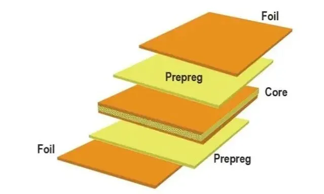
Engineers designing greenhouse sensor PCBs start with schematic capture emphasizing modularity for future upgrades. Component selection prioritizes low-power devices to extend battery life in remote nodes. PCB stackups use at least four layers for better signal integrity and power distribution in noisy environments. Trace routing follows length-matching for differential pairs in communication lines. Solder mask and silkscreen enhance identification and protection during assembly.
Moisture mitigation is paramount, with conformal coatings applied per IPC-CC-830 guidelines to repel humidity and contaminants. Baking and dry packing procedures align with IPC/JEDEC J-STD-033D for handling moisture-sensitive devices before installation. These steps prevent delamination or ionic migration in high-humidity settings.
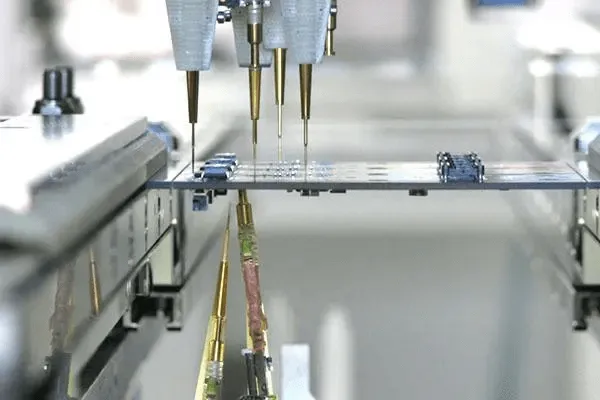
Layout considerations include thermal vias under power regulators to dissipate heat from enclosed housings. EMI suppression via ferrite beads and capacitors shields sensor signals. Testing protocols verify functionality under simulated greenhouse conditions, such as cyclic humidity exposure.
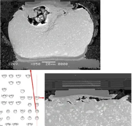
Assembly processes adhere to IPC J-STD-001J requirements for soldered interconnections, ensuring void-free joints resistant to vibration. Qualification testing per IPC-6012F confirms board performance in class 2 or 3 environments suitable for continuous operation.
System Integration and Troubleshooting Insights
Integrating multiple sensor PCBs requires a central hub with standardized interfaces like I2C or SPI buses. Power budgeting across boards prevents voltage drops during peak loads. Enclosures with IP-rated seals protect against dust and water ingress. Firmware handles sensor fusion for predictive control, adjusting ventilation preemptively.
Common troubleshooting involves oscilloscope checks for noise on sensor lines, often traced to poor grounding. Humidity-induced failures manifest as erratic readings, resolved by recoating or component replacement. Firmware debugs log errors for root cause analysis. Periodic calibration maintains accuracy amid sensor aging.
Conclusion
Sensor PCBs enable precise greenhouse automation by optimizing climate parameters through integrated temperature and humidity sensing, light detection, CO2 tracking, and ventilation control. Electric engineers achieve reliability via thoughtful design, moisture protection, and adherence to proven standards. These systems reduce operational costs while boosting productivity. Future advancements may incorporate edge AI for autonomous adjustments. Implementing these principles ensures robust, scalable solutions for modern greenhouses.
FAQs
Q1: What is a greenhouse climate control PCB?
A1: A greenhouse climate control PCB centralizes sensors and controllers for monitoring temperature, humidity, CO2, and light while driving ventilation actuators. It processes real-time data to maintain ideal conditions, using microcontrollers for logic and interfaces for peripherals. Design emphasizes low noise and humidity resistance for long-term deployment. This integration minimizes wiring complexity and enhances system responsiveness in variable environments.
Q2: How does a temperature and humidity sensor PCB improve greenhouse efficiency?
A2: A temperature and humidity sensor PCB delivers accurate environmental data for automated adjustments, preventing stress on plants from extremes. Signal conditioning ensures reliable readings despite condensation challenges. Placement strategies optimize coverage across zones. Paired with ventilation, it reduces energy use by activating fans only when needed. Troubleshooting focuses on seal integrity to avoid corrosion.
Q3: Why is light sensor PCB design critical for greenhouse automation?
A3: Light sensor PCB design captures intensity for dynamic shading or LED supplementation, matching plant needs across growth stages. Amplifiers convert weak signals effectively, with shielding against EMI. Calibration features adapt to seasonal changes. Integration with timers automates photoperiod control. Proper design cuts lighting costs while maximizing yields.
Q4: What role does a CO2 monitoring PCB play in automated ventilation?
A4: A CO2 monitoring PCB detects enrichment levels to trigger ventilation, balancing photosynthesis without excess loss. Stable power and optical isolation maintain precision. Threshold logic links directly to actuators. In humid greenhouses, coatings protect against failures. This setup optimizes air quality and resource use efficiently.
References
IPC-6012F — Qualification and Performance Specification for Rigid Printed Boards. IPC, 2023
IPC J-STD-001J — Requirements for Soldered Electrical and Electronic Assemblies. IPC, 2024
IPC/JEDEC J-STD-033D — Handling, Packing, Shipping and Use of Moisture/Reflow Sensitive Surface Mount Devices. IPC/JEDEC, 2018
IPC-CC-830B — Qualification and Performance of Electrical Insulating Compounds for Conformal Coatings. IPC, 2013