PCB mounting bracket design mistakes frequently cause assembly issues, mechanical failures, and costly rework. Even a simple sheet metal bracket can create big problems if strength, hole positioning, and deformation aren't carefully considered during the design phase.
After years of reviewing mechanical drawings alongside PCB layouts, these are the recurring issues that show up in production.
Underestimating Bracket Strength and Material Thickness
Many PCB mounting bracket design efforts focus only on fit, ignoring dynamic loads and vibration. Thin sheet metal that looks adequate on screen often flexes under the weight of the board and components during shipping or operation.
Typical failure modes include bending at mounting tabs or fatigue cracking around screw holes after repeated thermal cycling.
Hole Position and Tolerance Issues
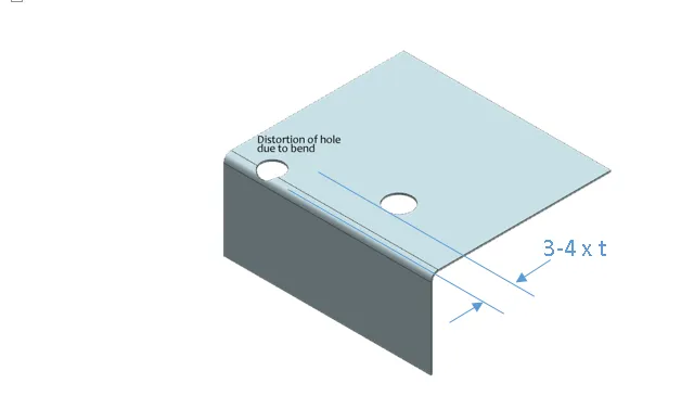
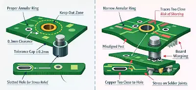
Misaligned hole patterns between the PCB and bracket are a top source of assembly headaches. Designers often use nominal dimensions without accounting for sheet metal tolerances or PCB fabrication tolerances.
In practice, ±0.1mm can make the difference between smooth assembly and forcing screws at an angle, which damages threads or cracks boards.
Clearance and Chamfer Considerations
Sharp edges around mounting holes create stress risers. Adding proper chamfers or using extruded holes improves both strength and alignment.
Warpage and Deformation During Fabrication and Assembly
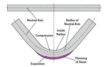
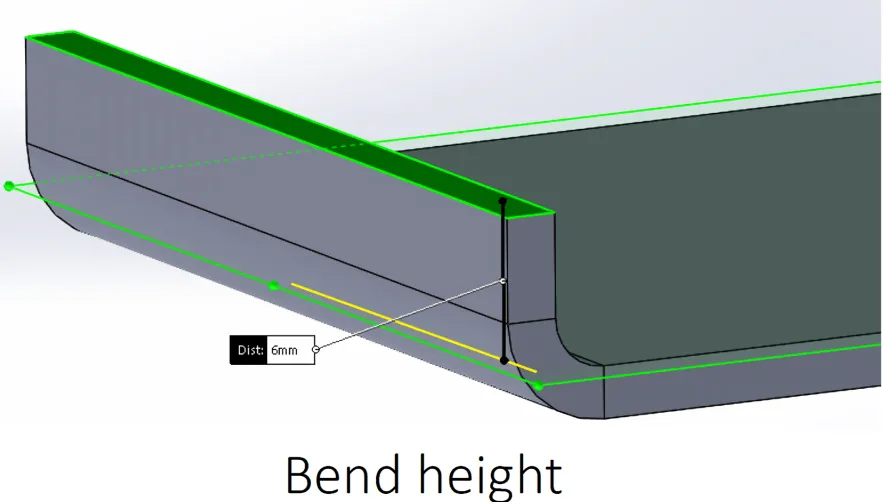
Sheet metal brackets easily deform during bending, welding, or powder coating processes. Poor PCB mounting bracket design that doesn't include adequate stiffening ribs or strategic bend reliefs leads to boards that don't sit flat or maintain proper standoff height.
This becomes critical in HDI or dense boards where component clearance is tight.

Inadequate Consideration of Thermal Expansion
Aluminum brackets paired with FR-4 boards create differential expansion. Without slotted holes or flexible mounting in at least one axis, this causes stress on solder joints or cracked vias over temperature cycles.
Mounting Hardware Interface Problems
Threaded inserts, PEM nuts, or standoffs that aren't properly specified create issues during volume assembly. Choosing the wrong hole size or ignoring minimum edge distances leads to weak connections or sheet metal tearing.
Vibration and Shock Performance
Brackets that pass static load checks often fail vibration testing because they lack proper damping or have resonant frequencies that align with product operating conditions.
Best Practices for Robust PCB Mounting Bracket Design
Use FEA analysis for critical applications. Add stiffening features early. Specify tolerances realistically for sheet metal processes. Coordinate hole patterns with PCB fabrication tolerances. Include clear notes on material, finish, and hardware requirements.
Prototype and test assemblies under real environmental conditions rather than assuming the design will behave as drawn. These steps prevent most common PCB mounting bracket design mistakes and deliver reliable mechanical integration.
Good bracket design is invisible in the final product. Bad design creates noise, rattles, and field failures that are expensive to fix.