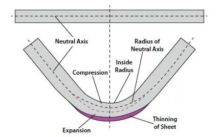
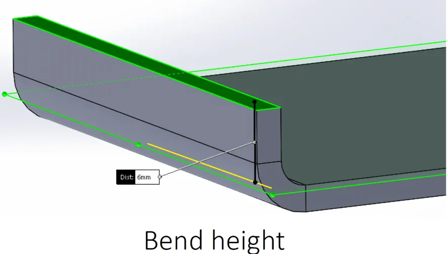
Sheet metal bending tolerance directly impacts how well your PCB fits into the final enclosure. What looks like a simple 90-degree bend on the drawing can introduce enough variation to cause alignment problems, stressed components, or impossible assembly.
Understanding these effects early prevents a lot of late-stage headaches during integration.
Bending Error Accumulation in Multi-Bend Parts
Each bend introduces positional error. On parts with several bends, these errors stack up quickly. A typical sheet metal bending tolerance of ±0.5mm per bend can result in several millimeters of deviation across a chassis with multiple folds.
This directly affects mounting hole locations relative to the PCB.
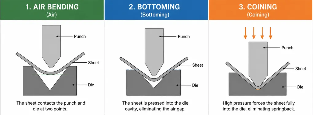
Springback and Material Behavior
Different materials and thicknesses exhibit varying springback after bending. Aluminum springs back more than steel. Thinner sheets are less predictable. Without compensation in the design or process, the final angle deviates from 90 degrees, tilting the PCB or shifting standoff heights.
Thickness and Grain Direction Effects
Bending parallel or perpendicular to the grain changes results. Ignoring this in sheet metal bending tolerance planning leads to inconsistent parts across production runs.
Impact on Assembly Clearance and Fit
Tight assembly gaps that look good in CAD become problematic when sheet metal bending tolerance is considered. What should be 0.2mm clearance can turn into interference or excessive slop, making automated or manual assembly difficult.
This is especially critical around connectors and tall components near enclosure walls.
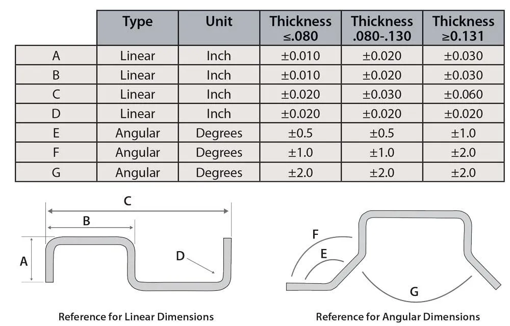
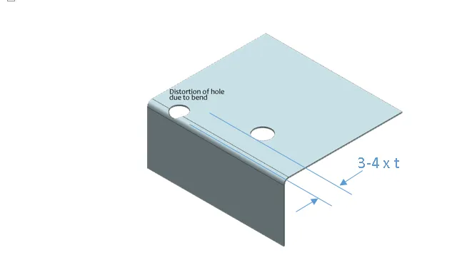
Hole Location Shift After Bending
Holes punched before bending move in both X/Y and angular position. Many PCB mounting bracket designs fail to account for this movement, resulting in misaligned screw holes that require manual adjustment during production.
Thermal and Mechanical Stress Transfer
Poorly controlled bends create residual stresses in the metal. When the enclosure heats up or experiences vibration, these stresses transfer to the PCB through mounting points, potentially cracking solder joints or traces.
Design Compensation Strategies
Using bend reliefs, larger tolerances on non-critical dimensions, and slotted holes in the PCB for floating mounts helps absorb variation.
Practical Recommendations for Better Integration
Specify realistic sheet metal bending tolerance on drawings. Perform tolerance stack-up analysis including the PCB and enclosure. Prototype with the actual fabrication process. Design in generous clearance around critical features and provide adjustment features where possible.
Coordinating early with both PCB and sheet metal suppliers prevents most assembly accuracy problems caused by bending variation.
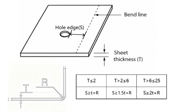
Sheet metal bending tolerance is not just a mechanical issue — it directly determines how easily and reliably your PCB integrates into the final product.