


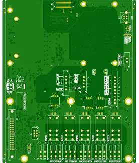
PCB Specifications
| Parameter | Value | Parameter | Value |
|---|---|---|---|
| PCB Type | FR4 PCB | Quantity | 15 pcs |
| Layers | 6 Layers | Board Type | Panel PCB |
| Dimensions | 192.53 x 149.86 mm | Copper Weight | 1oz |
| Thickness | 1.6 mm | Min Track / Spacing | 4/4mil |
| Surface Finish | ENIG (Immersion Gold) | Min Hole Size | 0.2mm |
| Solder Mask | Green | Silkscreen | White |
| Stack-up | Custom | Impedance Control | Yes |
Manufacturing Timeline
Logistics Information
Key Manufacturing Processes
Manufacturing Summary
This 6-layer FR-4 board measured 192.53 × 149.86 mm with 1.6 mm thickness, asymmetric copper weights of 0.5 oz inner and 1 oz outer layers, and TG170 material. The small 15-piece order required controlled impedance including 50 ohm and 90 ohm lines at 4 mil minimum trace/space, ENIG finish, and via tenting. Production used AIVON panelization with 4 mm process edges and V-scoring for separation, completed within a tight 4-day lead time.
The customer stackup differed from standard, necessitating confirmation and adjustment to production norms while preserving impedance targets. Line width and spacing for 90 ohm inner layers were swapped per gerber review to achieve specified values. Selected vias lacked mask openings on both sides, which was clarified for proper tenting. A notable concern involved the 50 ohm line on L4 lacking copper pour for shielding, risking inaccurate impedance readings; this was addressed through stackup verification and trace optimization. Silkscreen markings for UL and date codes were positioned as requested after file confirmation.
All DFM adjustments were implemented and re-verified with updated files before release to lamination and plating. Final 100% flying probe testing confirmed impedance values and continuity. The boards met electrical and mechanical requirements with reliable delivery. Further details on the impedance stackup adjustment and shielding verification are available in the engineering case study.
Explore More PCB Manufacturing Resources
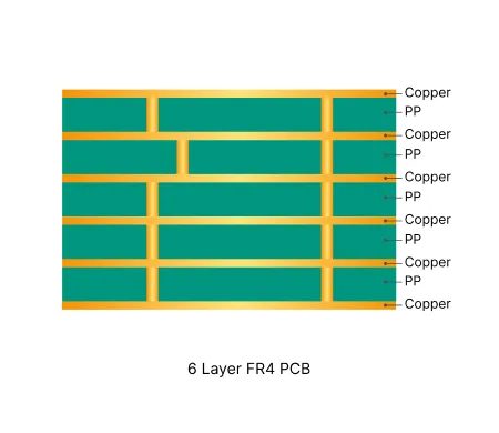
6 Layer FR4 PCB Manufacturing Insights
Six layer FR4 boards provide optimized routing density and power distribution. They require precise lamination and plating process control to maintain yield and reliability.
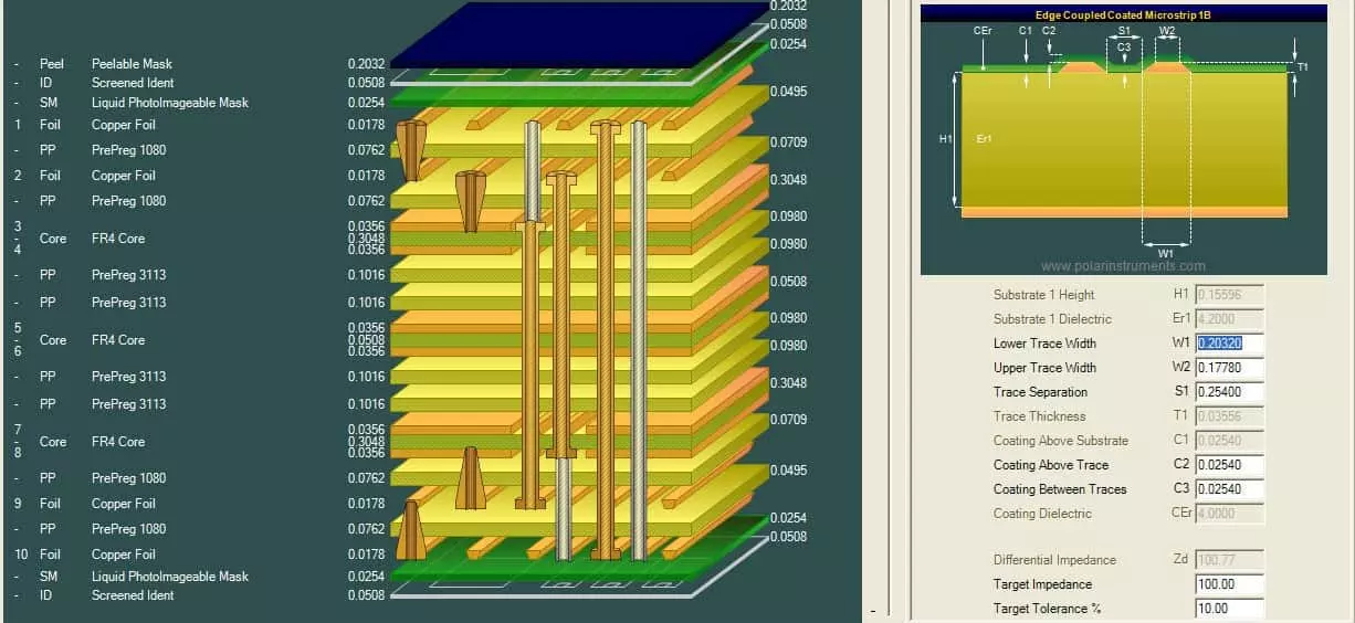
How to Avoid Common Engineering Queries in Multilayer FR4 PCB Design
Real multilayer FR4 PCB CAM review cases covering stack-up confirmation, impedance control, copper balance, via tenting, and edge clearance EQs. Discover practical DFM best practices for 4-layer and higher boards to reduce engineering queries, prevent warpage, and improve first-pass yield.
Real Production Records
| Order ID | PCB Type | Layers | Dimensions | Solder Mask | Surface Finish | Quantity | Action |
|---|---|---|---|---|---|---|---|
| FR4-20260918-033 | FR4 PCB | 6 | 55 x 41.7 | Green | ENIG (Immersion Gold) | 5 | View detail |
| FR4-20260912-059 | FR4 PCB | 2 | 275 x 193.7 | Green | ENIG (Immersion Gold) | 100 | View detail |
| FR4-20260819-043 | FR4 PCB | 10 | 157 x 140 | Blue | ENIG (Immersion Gold) | 100 | View detail |


