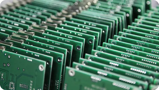
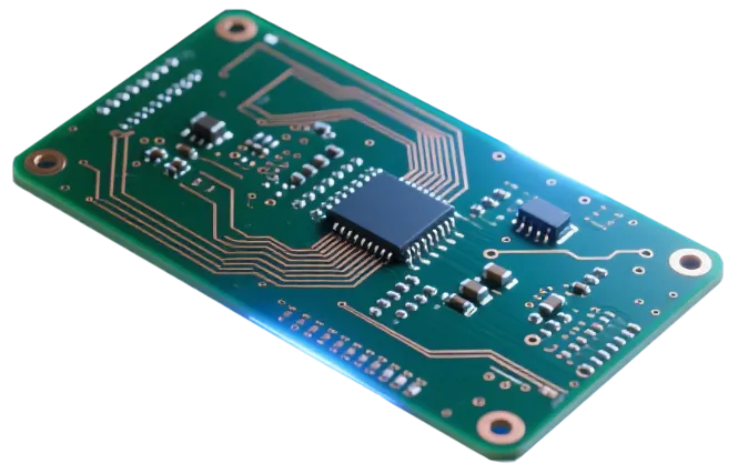
Discover how AIVON manufactures 6 Layer FR4 PCBs, including multilayer stackup optimization, impedance control requirements, fabrication processes, manufacturing challenges, and real production experience from customer orders.
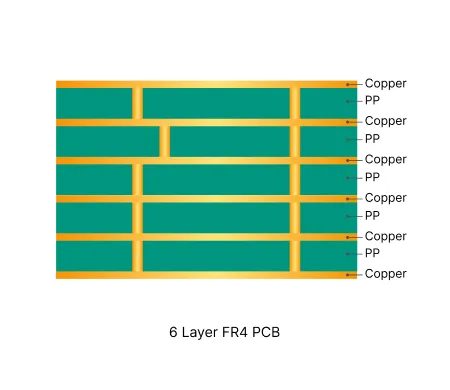
| Parameter | Typical Range |
|---|---|
| Layer count | 6 layers |
| Material type | FR4 TG130 to TG170 |
| Surface finish | ENIG, HASL, OSP |
| Thickness | 0.8 mm to 3.0 mm |
| Solder mask | Green, black, red, white, yellow, blue, purple, matte black, matte black |
| Copper thickness | 1 oz to 4 oz |
| Special features | Impedance control, blind vias, buried vias, via-in-pad |
Inner Layer Imaging & Etching Multiple cores are imaged and etched with high registration accuracy. Precise annular-ring control and etch-factor compensation on inner layers are essential to maintain impedance and via reliability across the six-layer structure.
Lamination & Stackup Control Cores and prepregs are stacked in a controlled sequence and laminated under heat and pressure. Symmetric copper distribution and dielectric thickness uniformity across all six layers are critical to minimize warpage, ensure layer-to-layer registration, and achieve consistent impedance.
Precision Drilling CNC drilling creates through-holes (and any controlled-depth features) with tight positional tolerance. Higher aspect ratios in 6-layer boards require optimized drill parameters to control hole-wall quality and registration to inner-layer pads.
Desmear & Plating Resin smear is thoroughly removed and electroless copper is deposited, followed by electrolytic plating. Uniform barrel plating through the full board thickness is vital for via reliability under thermal cycling.
Outer Layer Patterning & Etching Outer layers are imaged, plated and etched. Trace compensation and reference-plane integrity are verified to meet controlled-impedance targets common on 6-layer designs.
Solder Mask & Via Treatment Solder mask is applied with accurate registration. Via tenting, resin plugging or open-window decisions are finalized here; conflicts between plugging and mask openings are resolved to protect surface planarity and solderability.
Routing, V-Scoring & Final Inspection Boards are separated by routing or V-scoring. Edge clearance, panelization integrity and copper-to-outline spacing are confirmed. 100% electrical testing and dimensional inspection ensure multilayer continuity and compliance before shipment.
| Order Quantity | Order Proportion | Estimated Price Level | Typical Lead Time |
|---|---|---|---|
| Prototype (<=30 pcs) | 58% | From $30 | From 2 days |
| Small volume (30-200 pcs) | 27% | From $80 | From 2 days |
| Mass production (>200 pcs) | 15% | From $140 | From 3 days |
| Order ID | PCB Type | Layers | Dimensions | Solder Mask | Surface Finish | Quantity | Action |
|---|---|---|---|---|---|---|---|
| Loading... | |||||||
AIVON medical device PCBs are high-reliability boards designed for healthcare applications. Built with strict quality control, biocompatible materials, and precise manufacturing, they ensure safety and accuracy. Suitable for diagnostic equipment, patient monitoring, and wearable medical devices, AIVON PCBs meet ISO and IPC medical standards.
Maximize power density and safety with AIVON’s specialized power supply PCBs. Engineered to handle high currents and thermal loads, our designs feature thick copper, thermal vias, and strict high-voltage isolation. We ensure superior efficiency and robust stability for applications ranging from chargers to industrial converters.
AIVON engineers rugged PCBs for industrial control systems demanding unwavering reliability in harsh environments. Featuring high-Tg materials, heavy copper, and conformal coatings, our solutions withstand extreme heat and vibration. We ensure superior signal integrity and long-term stability for PLCs, robotics, and drives, maximizing your operational uptime.
AIVON manufactures 6 Layer FR4 PCB with precise stackup control, strict multilayer alignment, and stable impedance management, ensuring signal integrity, high interlayer reliability, and consistent mass production quality.

Learn how to design a reliable 6 layer PCB stackup for high-current and high-voltage power electronics. This guide covers 6 layer board stackup principles, copper weight, thermal management, creepage and clearance, and isolation techniques for optimal performance.
Read More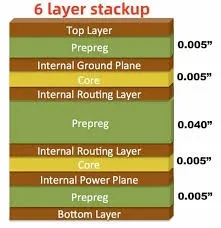
Learn how to design a reliable 6-layer PCB stackup with proper impedance control and signal layer placement for superior EMI/EMC compliance. This guide covers grounding, shielding, filtering, and practical stack-up configurations to help your board pass EMC testing on the first attempt
Read More










.webp)