Coupons
Help
  • FAQ
    browse most common questions
  • Live Chat
    talk with our online service
  • Email
    contact your dedicated sales:

2 Layer FR4 PCB Manufacturing Insights

Discover how AIVON manufactures 2 Layer FR4 PCBs, including double-sided circuit structures, reliable through-hole fabrication processes, manufacturing challenges, and real production experience from customer orders.
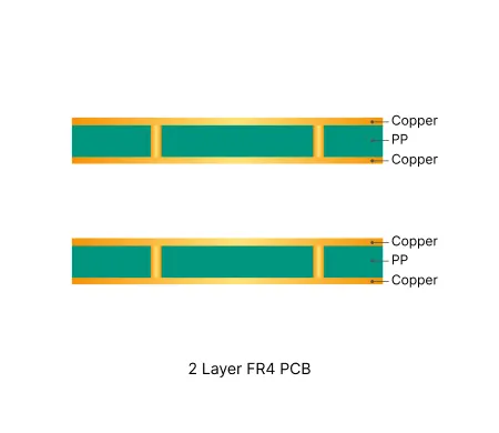
Typical Specification Range

0x2y6g-compress
Parameter Typical Range
Layer count2 layers
Material typeFR4 TG130 to TG170
Surface finishHASL, ENIG, OSP
Thickness0.8mm - 2.0mm
Solder maskGreen, black, red, white, yellow, blue, purple, matte black, matte black
Copper thickness1oz - 6oz
Special featuresPlated through holes, castellated holes

Manufacturing Process Insights

Material Preparation & Lamination FR4 core is laminated with copper foil under controlled heat and pressure. Symmetrical copper weight is critical to minimize warpage on thin or large panels.


Precision Drilling CNC drilling forms all through-holes. Parameters and tooling are optimized for holes >2.0 mm or high-aspect-ratio boards to control wall roughness, diameter tolerance and registration.


Desmear & Electroless Copper Resin smear is removed and electroless copper deposited to establish conductivity. Uniform coverage at this stage determines long-term via reliability.


Pattern Imaging & Etching Dry film defines the circuit pattern, followed by controlled etching. Precise registration and etch compensation prevent undercut and open circuits on tight features.


Solder Mask Application Liquid photoimageable mask is applied and developed. Via tenting vs open-window decisions are finalized here to avoid ink intrusion and exposed copper.


Surface Finish HASL, ENIG or OSP is selected based on solderability, cost and shelf life. Process control ensures uniform coverage while maintaining dimensional stability.


Routing, V-Scoring & Depanelization Boards are separated by routing, V-scoring or both. Tab width, stamp holes and copper-to-edge clearance are verified to prevent breakage and edge defects.


Electrical Test & Final Inspection 100% electrical testing confirms continuity and isolation. Final inspection against IPC criteria ensures only compliant boards are shipped.

Manufacturing Order Profile

Order Quantity Order Proportion Estimated Price Level Typical Lead Time
Prototype (<=30 pcs) 62% From $1 From 1 Day
Small volume (30-200 pcs) 26% From $30 From 1 Day
Mass production (>200 pcs) 12% From $50 From 1 Day

Manufacturing Challenges & Process Optimization

Via Tenting / Open Via Conflict
Via treatment frequently mismatches between system order notes and Gerber solder mask data.
Designers often specify “open vias” while Gerber shows partial or full tenting (or vice versa).
This leads to inconsistent HASL results, solder bead entrapment, ink intrusion into barrels, exposed copper at via mouths, and long-term reliability risks (oxidation, intermittent connections) that fail IPC-A-600 criteria.

✓ Confirm exact via treatment (full tenting / selective tenting / open) with annotated screenshots before CAM release.
✓ Regenerate solder mask layers to strictly match confirmed intent and apply consistent expansion.
✓ For thick boards (>3 mm) or high-aspect-ratio vias, pre-compensate drill size (e.g. 0.4 mm → 0.6 mm) to improve tenting reliability.

View Exact Order Case

Undersized Panel Connection Tabs & Depanelization Breakage
Customer-supplied panels often use connection tabs that are too narrow for the board thickness (especially 1.0 mm boards).
During routing or manual separation the tabs fracture at the root, causing board breakage, jagged edges, and damage to nearby copper features.
Zero-process-edge designs amplify the mechanical stress and significantly raise scrap rates.

✓ Widen tabs to process-proven minimum width according to board thickness and add stamp holes (mouse bites) for controlled break points.
✓ Align single-board outline and panel array geometry from the same source file to eliminate registration errors.
✓ Verify panel strength against IPC-A-600 edge-condition criteria before releasing production files.

View Exact Order Case

Insufficient Copper-to-Edge / Pad-to-Outline Clearance
Pads, traces or copper features are frequently placed closer than 0.3–0.5 mm to the final board outline, especially on V-cut panels.
After routing or V-scoring the copper becomes exposed, creating short-circuit, corrosion and cosmetic defects that violate Class 2/Class 3 requirements.
Large panels amplify registration tolerance stack-up and make the problem more severe.

✓ Enforce minimum 0.3–0.5 mm clearance between any copper feature and final outline on V-cut or routed boards.
✓ Adjust V-scoring depth and path to avoid copper or legend interference; confirm with customer annotated drawings.
✓ Add process-edge copper clearance compensation in CAM when zero-process-edge is specified.

View Exact Order Case

Tight Hole Tolerances & Missing Annular Rings / Mask Openings
Press-fit or large-diameter holes (>2.0 mm) are often given tolerances tighter than process capability (drill run-out, spindle variation, panel size effects).
Many PTH holes are designed with pad diameter equal to drill size (zero annular ring) or completely lack solder-mask openings.
Results include incomplete plating, weak barrel adhesion, ink-covered pads, insertion force problems and Class 3 reliability failures.

✓ Negotiate realistic, process-capable tolerances for holes >2.0 mm based on actual drill physics and panel size.
✓ Enforce minimum annular-ring requirements and automatically add proper solder-mask openings on all PTH pads.
✓ Convert ambiguous NPTH/PTH definitions and update drill programs only after customer written confirmation.

View Exact Order Case

Solder-Mask Bridge Failure on Tight Pad Spacing
Pad-to-pad or line-to-pad spacing is frequently designed at 4 mil while reliable solder-mask bridge formation requires ≥7–8 mil.
Especially common around dense connectors or BGA-adjacent areas.
Broken mask bridges cause solder shorts during assembly, exposed copper, and high field-failure rates.

✓ Flag any spacing below process minimum and propose either spacing increase or acceptance of potential mask defects.
✓ Prioritize solder-mask integrity over silkscreen when conflicts occur; regenerate mask layers after confirmation.
✓ For heavy-copper (3 oz) boards, further relax spacing and apply etching compensation to prevent undercut-induced shorts.

View Exact Order Case

Design Considerations

Via Treatment Strategy
Always generate solder-mask Gerber layers that exactly match the via treatment stated in the order notes or fabrication notes. For selective tenting, provide a clear list or graphical call-outs of which vias are tented. On boards thicker than 3 mm, evaluate drill compensation early to ensure reliable tenting and plating. Open vias should be reserved only when probe or soldering access is truly required.
Panelization & Mechanical Strength
Edge Clearance & Outline Integrity
Hole Definition, Tolerances & Annular Rings
design-standard-fr4-pcb-compress

Real Production Records

Order ID PCB Type Layers Dimensions Solder Mask Surface Finish Quantity Action
Loading...

Related Products

Common Applications

PCB Solution for Consumer Electronics

AIVON's consumer electronics PCBs are precision-engineered for smartphones, tablets, laptops, and smart home devices. Using HDI design, fine-line etching, and multilayer fabrication, they deliver compact layouts, high-speed signal transmission, and strong reliability while meeting international quality and environmental standards.

PCB Solution for Industrial Control

AIVON engineers rugged PCBs for industrial control systems demanding unwavering reliability in harsh environments. Featuring high-Tg materials, heavy copper, and conformal coatings, our solutions withstand extreme heat and vibration. We ensure superior signal integrity and long-term stability for PLCs, robotics, and drives, maximizing your operational uptime.

PCB Solution for Telecommunication

AIVON telecommunication PCBs are high-performance boards designed for fast and stable signal transmission. Used in base stations, routers, satellite systems, and 5G infrastructure, they feature advanced materials and precision manufacturing to ensure low signal loss, accurate impedance control, and reliable high-frequency performance.

View More Engineering Resources

Why Choose AIVON for 2 Layer FR4 PCB?

AIVON produces 2 layer FR4 PCBs with precise FR4 material control for thermal stability. Double-sided drilling, plating and etching ensure tight tolerances on traces and vias for reliable performance.
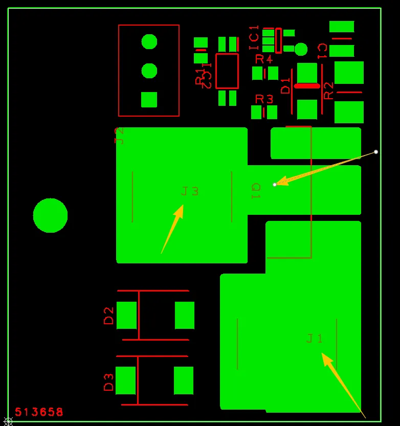
Quote FR4 PCB Now
Common Engineering Queries in 2 Layer FR4 PCB Design and Manufacturing

Common Engineering Queries in 2 Layer FR4 PCB Design and Manufacturing

Real Engineering Queries (EQ) and DFM issues for 2 Layer FR4 PCB (double-sided boards) from actual production reviews. Learn how to avoid common problems with via treatment, silkscreen on pads, solder mask openings, hole attributes, board edge clearance, and other frequent design pitfalls.

Read More
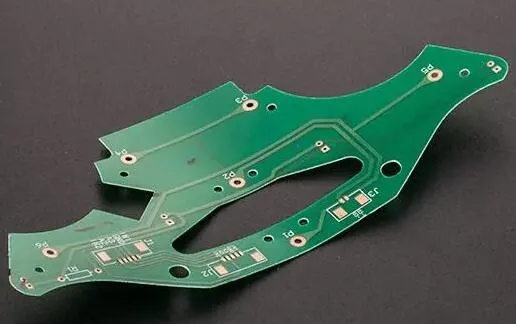
FR-4 PCB Design Fundamentals: A Beginner's Step-by-Step Guide

FR-4 PCB Design Fundamentals: A Beginner's Step-by-Step Guide

Learn the basics of FR-4 PCB design, from material understanding to creating single and double-layer boards using popular software like KiCad, Eagle, and Altium.

Read More

2026 AIVON.COM All Rights Reserved
Intellectual Property Rights | Terms of Service | Privacy Policy | Refund Policy