Typical Specification Range
| Parameter | Typical Range |
|---|---|
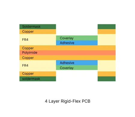
| Layer count | 4 layers |
| Material type | Polyimide flex with FR-4 rigid cores |
| Surface finish | ENIG, OSP, Immersion Silver |
| Thickness | Rigid board thickness 0.3mm - 1.6mm, FPC Thickness 0.08mm - 0.15mm |
| Solder mask | LPI solder mask and polyimide coverlay |
| Copper thickness | 0.5oz to 2oz |
| Special features | Controlled impedance, bend radius control, stiffener attachment |
Manufacturing Process Insights
Lamination bonds rigid FR-4 to polyimide flex layers using precise temperature and pressure profiles.
Drilling combines laser and mechanical methods to create vias while protecting flex areas.
Plating applies uniform copper in transition zones to ensure reliable electrical continuity.
Surface finish selection balances solderability on rigid sections with flexibility requirements.
Registration control and material compatibility testing reduce delamination risks during sequential lamination.
Manufacturing Order Profile
| Order Quantity | Order Proportion | Estimated Price Level | Typical Lead Time |
|---|---|---|---|
| Prototype (<=30 pcs) | 76% | From $400 | From 13 days |
| Small volume (30-200 pcs) | 18% | From $520 | From 15 days |
| Mass production (>200 pcs) | 6% | From $800 | From 18 days |
Manufacturing Challenges & Process Optimization
Design Considerations
Related Products
Common Applications
PCB Solution for Consumer Electronics
AIVON's consumer electronics PCBs are precision-engineered for smartphones, tablets, laptops, and smart home devices. Using HDI design, fine-line etching, and multilayer fabrication, they deliver compact layouts, high-speed signal transmission, and strong reliability while meeting international quality and environmental standards.
PCB Solution for Medical Devices
AIVON medical device PCBs are high-reliability boards designed for healthcare applications. Built with strict quality control, biocompatible materials, and precise manufacturing, they ensure safety and accuracy. Suitable for diagnostic equipment, patient monitoring, and wearable medical devices, AIVON PCBs meet ISO and IPC medical standards.
PCB Solution for Aerospace and Aviation
AIVON provides high-reliability PCBs designed for civil aviation and aerospace applications, built to perform under extreme conditions such as vibration, temperature variation, and high-altitude environments. These PCBs are widely used in avionics systems, flight control modules, communication equipment, and satellite technologies. With advanced multilayer structures, heavy copper options, and high-temperature materials, our solutions are engineered to meet stringent reliability standards such as IPC-6012 Class 3.
Real Production Records
| Order ID | PCB Type | Layers | Dimensions | Solder Mask | Surface Finish | Quantity | Action |
|---|---|---|---|---|---|---|---|
| Loading... | |||||||
View More Engineering Resources
Why Choose AIVON for 4 Layer Rigid-Flex PCB?
AIVON masters complex 4-layer rigid-flex integration. We ensure precise stack-up alignment, reliable transition zone bonding, and thermal stress control for high-density, durable interconnect solutions.
The Ultimate Guide to Rigid-Flex PCB Manufacturing: Mastering Complexity and Reliability at Scale
Navigate the full lifecycle of Rigid-Flex PCB Manufacturing. From solving high-density thermal challenges to scaling from prototype to production, master the tech and strategies for modern electronics.
Read More
The Ultimate Guide to Rigid-Flex PCB Design: Mastering Reliability, Complexity, and Cost
Master the complexities of Rigid-Flex PCB Design with this 2,500-word guide. Explore stack-up symmetry, bend radius calculations, via optimization, and cost-effective manufacturing strategies.
Read More


