










PCB Specifications
| Parameter | Value | Parameter | Value |
|---|---|---|---|
| PCB Type | Rigid-Flex PCB | Quantity | 10 pcs |
| Layers | 4 Layers | Board Type | Panel PCB |
| Dimensions | 133.69 x 160.84 mm | Copper Weight | 1OZ |
| Thickness | 0.8 mm | Min Track / Spacing | 6/6mil↑ |
| Surface Finish | ENIG (Immersion Gold) | Min Hole Size | 0.3mm↑ |
| Solder Mask | Matte Black | Silkscreen | White |
Manufacturing Timeline
Logistics Information
Key Manufacturing Processes
Manufacturing Summary
This 4-layer rigid-flex PCB order (H4P-879-AI17690A) involved a board size of 133.69 × 160.84 mm, 0.8 mm rigid thickness, and a total quantity of 20 pieces (10 sets). The design combined rigid FR-4 sections with flexible areas using double-sided yellow coverlay on the flex portion and matte black solder mask on the rigid areas. ENIG surface finish was applied with specified gold and nickel thicknesses, along with 0.3 mm minimum hole size and 6 mil line width/spacing. The stackup featured 1 oz copper on inner and outer layers, with PI stiffener reinforcement on the flex region reaching 0.3 ± 0.05 mm total thickness after adjustment. Single-piece shipping was confirmed per customer requirements.
During DFM review, several critical issues required resolution to ensure manufacturability and reliability. The original via placement near the flex-rigid transition zone posed a high risk of chemical ingress during processing, which could lead to delamination or scrap; vias were relocated to maintain adequate clearance. Gold finger to outline spacing was tightened, leading to a controlled 0.2 mm trim on the production artwork. Inner corners in the flex-rigid junction were modified to 0.5 mm radius to prevent tearing during handling and assembly. Bottom layer silkscreen data issues were resolved by confirming single-sided printing aligned with customer intent. Stackup and PI stiffener thicknesses were iteratively verified to meet both mechanical and electrical requirements.
All engineering changes were implemented and approved prior to production, with full flying probe testing and IPC Class II inspection completed successfully. The order was delivered within the 7-day window with consistent quality across the batch. For detailed analysis of the rigid-flex DFM transition controls applied in this sensor board production, refer to the engineering case documentation.
Explore More PCB Manufacturing Resources
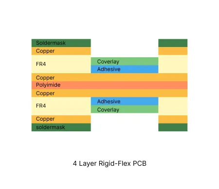
4 Layer Rigid-Flex PCB Manufacturing Insights
4 layer rigid-flex constructions deliver high density circuitry with mechanical flexibility for aerospace, medical, and industrial applications.
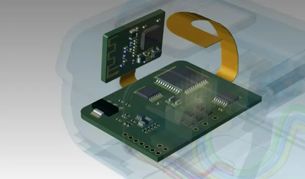
The Ultimate Guide to Rigid-Flex PCB Design: Mastering Reliability, Complexity, and Cost
Master the complexities of Rigid-Flex PCB Design with this 2,500-word guide. Explore stack-up symmetry, bend radius calculations, via optimization, and cost-effective manufacturing strategies.
Real Production Records
| Order ID | PCB Type | Layers | Dimensions | Solder Mask | Surface Finish | Quantity | Action |
|---|---|---|---|---|---|---|---|
| RFP-20260723-038 | Rigid-Flex PCB | 4 | 186 x 111.6 | Green | ENIG (Immersion Gold) | 10 | View detail |
| RFP-20260626-0002 | Rigid-Flex PCB | 4 | 100 x 106.01 | Green | ENIG (Immersion Gold) | 5 | View detail |
| RFP-20260608-0005 | Rigid-Flex PCB | 4 | 22.15 x 97.92 | Green | ENIG (Immersion Gold) | 20 | View detail |


