










Custom Video Interface PCB: Reliable Prototyping for Discrete Logic Displays
Key Moment
Project Background
In the world of custom computing and retro-inspired hardware, few challenges capture the pure engineering spirit like generating real video output from discrete logic alone. Spencer of JurassicVader set out to build a true video interface for his from-scratch computer—no FPGA, no microcontroller video core, just counters, gates, RAM, and precise timing. The goal was a clean black-and-white 400×300 display capable of readable text and eventual graphics, something far beyond simple LED blink patterns.
This ambition reflects a broader market need among makers, educators, and embedded engineers who value educational clarity and absolute control over every gate and nanosecond. Breadboards excel at teaching concepts, yet they introduce parasitics, intermittent contacts, and inconsistent delays that become critical when a pixel clock starts running. For projects aiming at a working monitor output that can later integrate with a custom CPU, reliable PCB design and manufacturing are non-negotiable. Spencer's journey, documented in his YouTube video "I made a Custom Video Interface (Watch out NVidia)", illustrates exactly why the leap from prototype tangle to professional board matters.
What This Video Covers
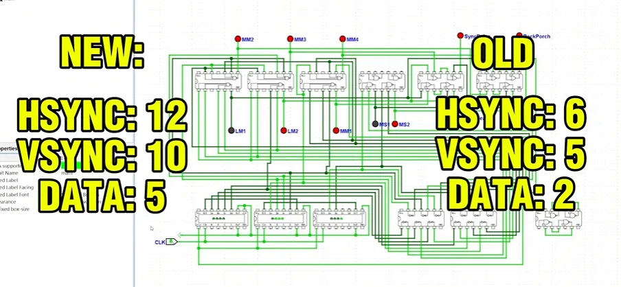
The video walks through Spencer's multi-month development process that began in October 2025. It starts with early breadboard attempts using only three boards and roughly thirteen ICs for basic horizontal and vertical timing plus data input. Viewers see the circuit evolve into a more deliberate design simulated in Logisim, expanding to twenty-seven ICs with cascaded counter chains. Horizontal timing counts to 528 and clocks the vertical counter that runs to 628, generating the necessary sync and blanking windows.
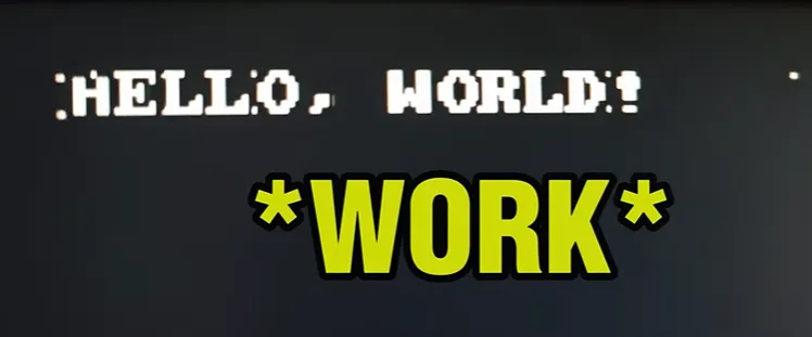
Pixel data is stored in RAM and serialized from sixteen-bit words into a one-bit stream (zero for black, one for white). The narrative covers the physical rebuilds, the testing phase where "Hello World" (or close equivalent) finally appeared on a real monitor, and the remaining artifacts that still needed resolution. Chapters include the first attempt, design phase restart, second physical build, and success testing. Throughout, the video highlights the maker's determination and the classic discrete-logic video challenges that appear once signals leave the ideal simulation environment.
Project Highlights and Key Features
- Fully discrete 74-series logic implementation delivering 400×300 black-and-white video without FPGA or microcontroller assistance.
- Cascaded counter architecture for precise horizontal and vertical timing, with intentional decoding of front-porch, sync, and back-porch windows.
- Parallel-to-serial conversion of RAM data into a clean pixel stream that paints lines left to right and advances vertically.
- Simulation-first workflow in Logisim that validated every timing edge before further physical builds.
- Proven path from multiple breadboard iterations to a functional monitor display showing readable text—an authentic "watch out NVIDIA" milestone for a home-designed system.
- Clear trajectory toward a compact, manufacturable PCB that consolidates the sprawling logic into a reliable form factor ready for CPU integration, color expansion, or higher resolution.
These strengths demonstrate both technical rigor and the educational value of understanding every propagation delay and signal path.
Challenges Encountered During Development
Spencer faced classic discrete-video timing problems that simulation alone could not fully eliminate. Cascade delay through 74x161 counters (approximately 14 ns each) produced 28–42 ns of skew at critical transitions such as 15→16 or 255→256. The result was brief windows of invalid RAM addresses that manifested as half-pixel glitches or "glitched bits" on the display.
Data serialization from parallel RAM words to a serial pixel stream introduced additional timing skew, forcing a complete rework after early tests yielded unreadable or inverted output. Breadboard parasitics—capacitance, intermittent contacts, and poor ground return paths—amplified already marginal timing into intermittent artifacts. Even higher-quality breadboards could not fully overcome long jumper wires. Small errors in NAND-decode logic for sync and blanking edges caused the monitor to lose lock or display extra pixels.
These issues are inherent to discrete-logic video at the speeds involved. While Logisim caught functional bugs, the physical builds revealed the analog realities of delay, noise, and parasitics that only a properly designed board can control.
How AIVON PCB Helps
AIVON PCB does not redesign the logic—that achievement belongs entirely to Spencer—but removes the manufacturing friction that prevents many ambitious discrete projects from reaching reliable hardware. A professional 4-layer FR-4 board with continuous ground and power planes dramatically reduces return-path inductance that amplifies counter-cascade glitches. Matched-length address and data routes keep the RAM interface clean. Local 100 nF ceramic decoupling placed within millimeters of every IC power pin becomes straightforward instead of a wiring challenge.
Quick-turn prototyping with welcome credits allows makers to iterate physical boards as rapidly as they iterate Logisim models. Expert DFM feedback on via sizes, copper balance, silkscreen clarity, and trace/space (targeting 0.15 mm minimum) catches the small issues that turn a "works on the bench" design into a board that powers up consistently every time. Precise fabrication tolerances keep the 14 ns counter delays repeatable from board to board rather than drifting with each new breadboard contact.
Recommended stack-up for this class of design includes 1.6 mm thickness, 1 oz copper, ENIG or lead-free HASL finish, and through-hole vias with 0.3 mm minimum drill. Impedance control is helpful but not mandatory at typical 10–25 MHz pixel rates; controlled 50 Ω digital traces plus good termination practice still improve edge quality. The same twenty-seven ICs that once sprawled across three breadboards fit onto a compact, rigid board with consistent inter-trace capacitance and solid mechanical integrity for future expansion.
AIVON's one-stop rapid PCB manufacturing, free DFM analysis, and reliable delivery transform the struggle into a finished product that can be mounted, shared, or expanded without fear of the next intermittent glitch.
Conclusion
Spencer's custom video interface proves that pure discrete logic can drive a real monitor and display readable text. The breadboard scars, Logisim late nights, and cascade-delay lessons are now part of the design DNA. Moving that circuit onto a properly manufactured 4-layer PCB elevates it from a fragile demonstration to a stable, camera-ready display ready for the custom CPU still to come.
Reliability rises, assembly time drops, and the project gains the mechanical foundation needed for color modules, higher resolution, or multi-board backplane integration. That is the quiet power of a trusted manufacturing partner: it lets the creator's vision survive contact with the real world.
If you are developing a custom computer, retro display controller, discrete video timing board, or any high-speed digital project currently living on a tangle of wires, the path from prototype to production-ready hardware is clearer than ever. Request a quote, claim your free DFM analysis, or start your next rapid PCB prototype with AIVON today—your monitor is waiting for the next "watch out NVIDIA" moment.
FAQ
Q1: Why choose discrete 74-series logic over an FPGA for a custom video interface?
A1: Discrete logic offers educational clarity and absolute control—every gate and nanosecond of delay remains visible and intentional. For from-scratch computer series this is the purest learning path. A well-designed PCB makes the size and power trade-offs practical.
Q2: How can cascade delay of 74x161 counters (≈14 ns each) be mitigated on a real PCB?
A2: Keep the cascade chain short and tightly routed, prefer synchronous enables over pure ripple where possible, and latch the final count with a register clocked on the opposite edge. A continuous ground plane further reduces the skew that breadboards exaggerate.
Q3: Is 400×300 a practical resolution for discrete video designs?
A3: Yes. It keeps counter widths and RAM size manageable while still delivering readable text and simple graphics. Many classic discrete VGA projects operate in the 200–400 pixel range for exactly this reason.
Q4: What PCB material and layer count work best for a first discrete video-timing board?
A4: Standard FR-4 with 4 layers is ideal. At these clock rates exotic low-loss materials are unnecessary, but continuous planes and proper local decoupling are essential to eliminate the artifacts seen on breadboards.
Q5: How many prototype spins should be budgeted when moving a video interface from breadboard to PCB?
A5: Plan for two. The first spin reveals layout-induced timing or noise issues; the second incorporates DFM and signal-integrity refinements. Quick-turn services with engineering feedback keep those iterations fast and affordable.
Hey, have you ever wondered how computers generate a video signal?
Well, luckily I need to explore this idea to complete my building a computer from scratch series.
As you know, I have been working on my video interface design for a while now, but I think it's about time to officially build this.
I would like to say that this was probably one of the most challenging builds I have done.
I'm not necessarily new to this anymore, as I've been pretty much fully immersed into this for almost a year now.
But when I tell you this was difficult, I really mean it.
I started to build this back in October 2025, and over a month or two of rebuilding the circuit multiple times, I decided to sit down and design the circuit in Logic Sim.
The first thing that we'll see when it comes to this design is that there are many more ICs, specifically 27, which is more than double the original amount.
What is important is that it works.
The idea is that I have two sets of counters.
The first counter can count up to 12 total bits, but we cut it off at 10 bits, specifically the decimal number 528.
Every time that the first counter makes it to 528, it will send one clock pulse to the other counter.
This counter will count to 628.
These are our horizontal and vertical timers.
The horizontal keeps track of where we are left to right, and our vertical keeps track of where we are up and down.
Simply how this circuit works is we write all of the pixels left and right on one line, and then we move down and do that exact same thing left to right.
This video is sponsored by Aivon.
If you're looking for quality and reliability, then you may want to check out Aivon.
They offer up to $60 in PCB prototype credit for new users.
After some alterations, my next test proved promising.
As you can see, there are still some visual artifacts going on, but I think there's still hope.
After a while I ended up getting a little overwhelmed and fully reworked the data serialization system.
And what is this? Oh wait, never mind, it's just inverted.
I managed to get more than some flashy colors on the screen.
As you can see, there are now words.
I will admit I did run into a few problems here and there.
My first test, as you can see, was hard to read. That is supposed to be an A by the way.
I will see you all in the next one.





