Introduction
High-frequency power amplifiers play a critical role in modern communication systems, radar applications, and wireless infrastructure. These devices operate at frequencies often exceeding several gigahertz, where signal integrity and power efficiency directly impact overall system performance. Rogers PCB materials stand out in this domain due to their engineered properties tailored for such demanding environments. Efficiency in power amplifiers hinges on minimizing losses while effectively managing generated heat, both of which Rogers PCBs address through superior dielectric and thermal characteristics. As engineers design for higher data rates and denser deployments, selecting the right PCB substrate becomes paramount to achieving reliable operation and extended lifespan. This article explores how Rogers PCB enhances efficiency in high-frequency power amplifier designs, from fundamental principles to practical implementation strategies.
What Are Rogers PCBs and Why They Matter for High-Frequency Power Amplifiers
Rogers PCBs refer to printed circuit boards fabricated using specialized high-frequency laminates developed by Rogers Corporation, typically incorporating ceramic-filled hydrocarbon or PTFE composites. These materials exhibit consistently low dielectric loss, stable dielectric constants across temperature and frequency ranges, and enhanced thermal conductivity compared to standard epoxy-based substrates. In high-frequency power amplifiers, where output powers can reach tens of watts, these properties translate to reduced signal attenuation and better heat dissipation. Power amplifiers generate significant heat from resistive losses in transistors and transmission lines, and any inefficiency compounds this issue, leading to thermal runaway or degraded performance. Rogers PCBs mitigate these challenges by offering low insertion loss, which preserves amplifier gain and linearity. Their dimensional stability also ensures reliable plated through-holes and minimal warpage under thermal stress, making them indispensable for applications like base stations and phased array radars.
The relevance extends to PCB design workflows, where engineers prioritize materials that support precise impedance control without compromising power handling. Traditional FR-4 substrates falter at microwave frequencies due to higher dissipation factors and moisture sensitivity, resulting in up to several dB of excess loss per stage. Rogers materials, by contrast, maintain performance stability, enabling higher efficiency metrics such as power-added efficiency. This is particularly vital in multi-stage amplifiers, where cumulative losses can drastically reduce output. Furthermore, their compatibility with standard fabrication processes lowers the barrier to adoption in production environments.
Technical Principles Behind Efficiency Gains with Rogers PCBs
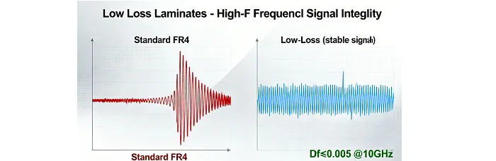
Efficiency in high-frequency power amplifiers relies on understanding loss mechanisms within the PCB substrate and traces. Dielectric losses, governed by the dissipation factor, dominate at elevated frequencies, converting signal energy into heat; Rogers PCBs feature inherently low dissipation factors, minimizing this effect. Conductor losses arise from skin effect and surface roughness, exacerbated in high-power scenarios where current densities peak; smoother copper interfaces on these laminates reduce such losses. Thermal coefficient of dielectric constant variations must also be low to prevent shifts in quarter-wavelength matching networks, which are sensitive to even minor impedance changes. These networks optimize power transfer from driver to output stages, and stable materials ensure consistent efficiency across operating temperatures.
Transmission line design further leverages Rogers PCB attributes. Microstrip and coplanar waveguide structures benefit from the substrate's uniform dielectric constant, enabling accurate 50-ohm impedance control essential for return loss below -20 dB. At high frequencies, radiation losses from discontinuities like bends or vias can degrade performance; the low-loss environment of Rogers materials confines fields effectively, reducing these parasitic effects. Heat generation scales with frequency due to thinner skin depths and increased power density, underscoring the need for high thermal conductivity to extract heat to sinks or chassis.
Rogers PCBs excel in power handling by balancing electrical and mechanical properties. Coefficient of thermal expansion closely matches copper, preventing delamination during soldering or operation. This reliability aligns with IPC-6012 qualification specifications for rigid printed boards, ensuring performance under thermal cycling.
Best Practices in PCB Design for High-Frequency Power Amplifiers Using Rogers Materials
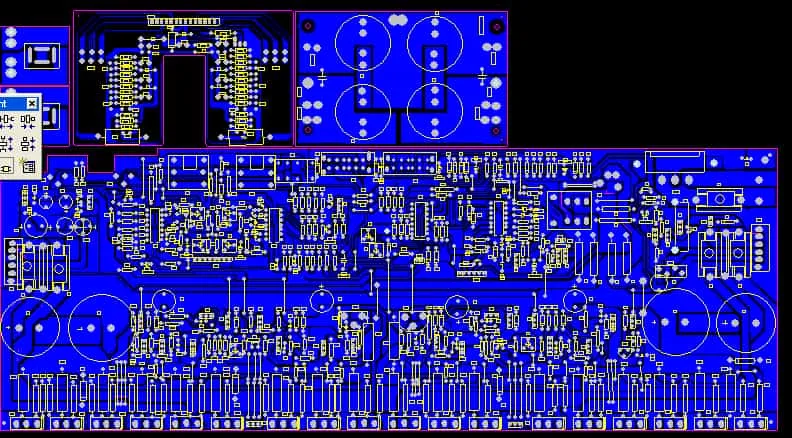
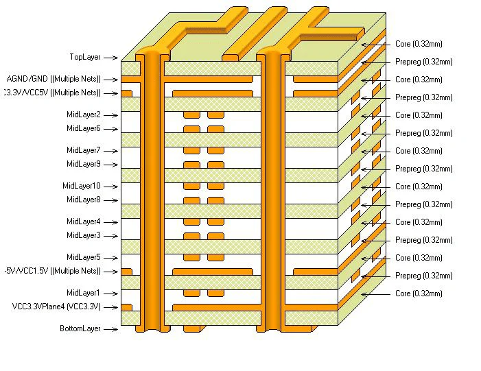
Selecting the appropriate Rogers PCB variant involves evaluating frequency range, power density, and thermal requirements early in the design phase. Engineers should model insertion loss using field solvers to predict efficiency, focusing on stackups with hybrid cores for multilayer boards. Optimal copper weight, typically 1-2 oz with low-profile electrodeposited foil, minimizes skin effect losses while supporting current capacity. Vias demand careful placement; blind or buried types reduce stub inductance, preserving high-frequency signals in matching circuits.
Thermal management practices are non-negotiable for efficiency. Integrate thermal vias under transistor flanges, arrayed in ground planes to channel heat vertically through the laminate. Substrate thickness influences both electrical length and power handling; thicker cores accommodate higher voltages but require adjusted trace widths. Heat sinks or embedded coins enhance dissipation, with simulations validating junction temperatures below critical thresholds.
Fabrication tolerances must adhere to IPC-A-600 acceptability criteria for high-frequency boards, emphasizing controlled impedance and minimal surface roughness. Decoupling capacitors placed close to power pins suppress noise, while ground plane stitching prevents cavity resonances. These strategies collectively boost power-added efficiency by reducing losses and stabilizing bias networks. In PCB design software, assign accurate material models for Rogers laminates, including frequency-dependent permittivity, to ensure simulation fidelity. Prototype validation through vector network analyzer sweeps confirms low S11/S21 deviations.
Troubleshooting and Optimization Insights for Rogers PCB Power Amplifiers
Common issues in high-frequency power amplifier PCBs include overheating from unmatched impedances or inadequate cooling. Symptoms manifest as compressed gain or intermodulation distortion; diagnose via infrared thermography to identify hotspots. Solutions involve refining matching networks with electromagnetic simulations, ensuring quarter-wave stubs align with the laminate's dielectric constant at operating temperature.
Warpage during assembly arises from CTE mismatches; Rogers materials' low Z-axis expansion minimizes this, but lamination with FR-4 hybrids requires symmetric builds. Solder joint reliability improves with low moisture absorption, aligning with JEDEC J-STD-020 moisture sensitivity classifications. Efficiency drops from via inductance call for staggered via fencing in transitions.
Optimization often yields through iterative thermal modeling, targeting dissipation factors that correlate with measured amplifier efficiency. Field upgrades, like adding thermal interface materials, recover performance in deployed units.
Conclusion
Rogers PCBs enable significant efficiency improvements in high-frequency power amplifiers through low-loss dielectrics, thermal robustness, and design flexibility. By addressing key loss mechanisms and supporting precise PCB design practices, these materials ensure reliable performance in demanding RF environments. Engineers benefit from stable operation, reduced heat buildup, and compatibility with industry standards. Implementing best practices in material selection, layout, and thermal management maximizes power-added efficiency while minimizing risks.
As a critical part of modern rogers PCB application development, these advanced laminates are widely used in RF power amplifiers for 5G infrastructure, radar systems, satellite communications, aerospace electronics, and automotive radar modules where signal integrity and thermal stability are essential. As applications push frequency and power limits, Rogers PCB remains a cornerstone for advancing amplifier technology.
FAQs
Q1: What properties make Rogers PCB ideal for high-frequency power amplifiers?
A1: Rogers PCB offers low dielectric loss tangent and stable dielectric constant, crucial for minimizing insertion loss in transmission lines. Enhanced thermal conductivity efficiently dissipates heat from high-power transistors, preventing efficiency degradation. Low moisture absorption ensures dimensional stability during assembly and operation, supporting reliable impedance control in PCB design.
Q2: How does Rogers PCB improve efficiency in power amplifier PCB design?
A2: In power amplifiers, Rogers PCB reduces dielectric and conductor losses, preserving signal power through multi-stage amplification. Stable thermal coefficients maintain matching network performance across temperatures, optimizing power transfer. This leads to higher power-added efficiency compared to standard substrates, especially at microwave frequencies.
Q3: What are key PCB design considerations for Rogers materials in high-frequency applications?
A3: Prioritize low-profile copper and controlled stackups for impedance accuracy. Incorporate thermal vias and heat sinks to manage power density. Adhere to fabrication tolerances for smooth surfaces, reducing skin effect losses and enhancing overall efficiency.
Q4: Why is thermal management critical in Rogers PCB power amplifiers?
A4: High-frequency operation amplifies losses, generating heat that shifts dielectric properties and reduces efficiency. Rogers PCB's superior conductivity channels heat effectively, stabilizing performance. Proper design prevents thermal runaway, ensuring long-term reliability in demanding environments.
References
IPC-6012E - Qualification and Performance Specification for Rigid Printed Boards. IPC, 2017
IPC-A-600K - Acceptability of Printed Boards. IPC, 2020
JEDEC J-STD-020E - Moisture/Reflow Sensitivity Classification. JEDEC, 2014