










PCB Specifications
| Parameter | Value | Parameter | Value |
|---|---|---|---|
| PCB Type | FR4 PCB | Quantity | 75 pcs |
| Layers | 10 Layers | Board Type | Panel PCB |
| Dimensions | 316.87 x 78.436 mm | Copper Weight | 1oz |
| Thickness | 1.5 mm | Min Track / Spacing | 6/6mil↑ |
| Surface Finish | ENIG (Immersion Gold) | Min Hole Size | 0.25mm |
| Solder Mask | Green | Silkscreen | White |
| Stack-up | Custom | Impedance Control | Yes |
Manufacturing Timeline
Logistics Information
Key Manufacturing Processes
Manufacturing Summary
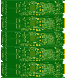
These 10-layer FR4 panel PCBs were produced as 75 units with panel dimensions of 316.87 × 78.436 mm and a finished board thickness of 1.5 mm. The custom stackup and impedance control requirements drove detailed stackup impedance engineering and trace width compensation prior to inner layer imaging and etching. High-pressure lamination maintained precise layer alignment across the elongated panel format while processing standard 1 oz copper and 6/6 mil geometry.
Green soldermask with white silkscreen was applied, followed by electroless nickel and immersion gold deposition to create a uniform ENIG surface finish. TDR impedance testing verified the controlled impedance parameters on the finished panels, after which full electrical testing confirmed continuity and isolation. The 0.25 mm minimum hole size fit comfortably within established drilling capabilities for this build.
The 53.5-day production window allowed complete execution of every process step without compromise, resulting in consistent panel quality and reliable electrical performance across the full order of these impedance controlled PCBs.
Explore More PCB Manufacturing Resources
High-Layer Count FR4 PCB Manufacturing
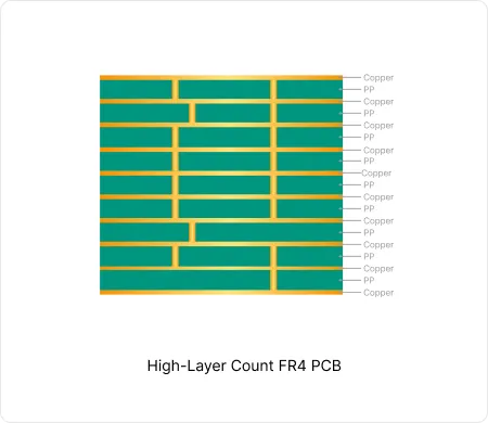
These high-layer count FR4 PCB enable high-density interconnects while maintaining signal integrity and thermal reliability in computing and communication equipment.
How to Resolve Gold Finger Bevel and Impedance EQs in 10-Layer PCBs
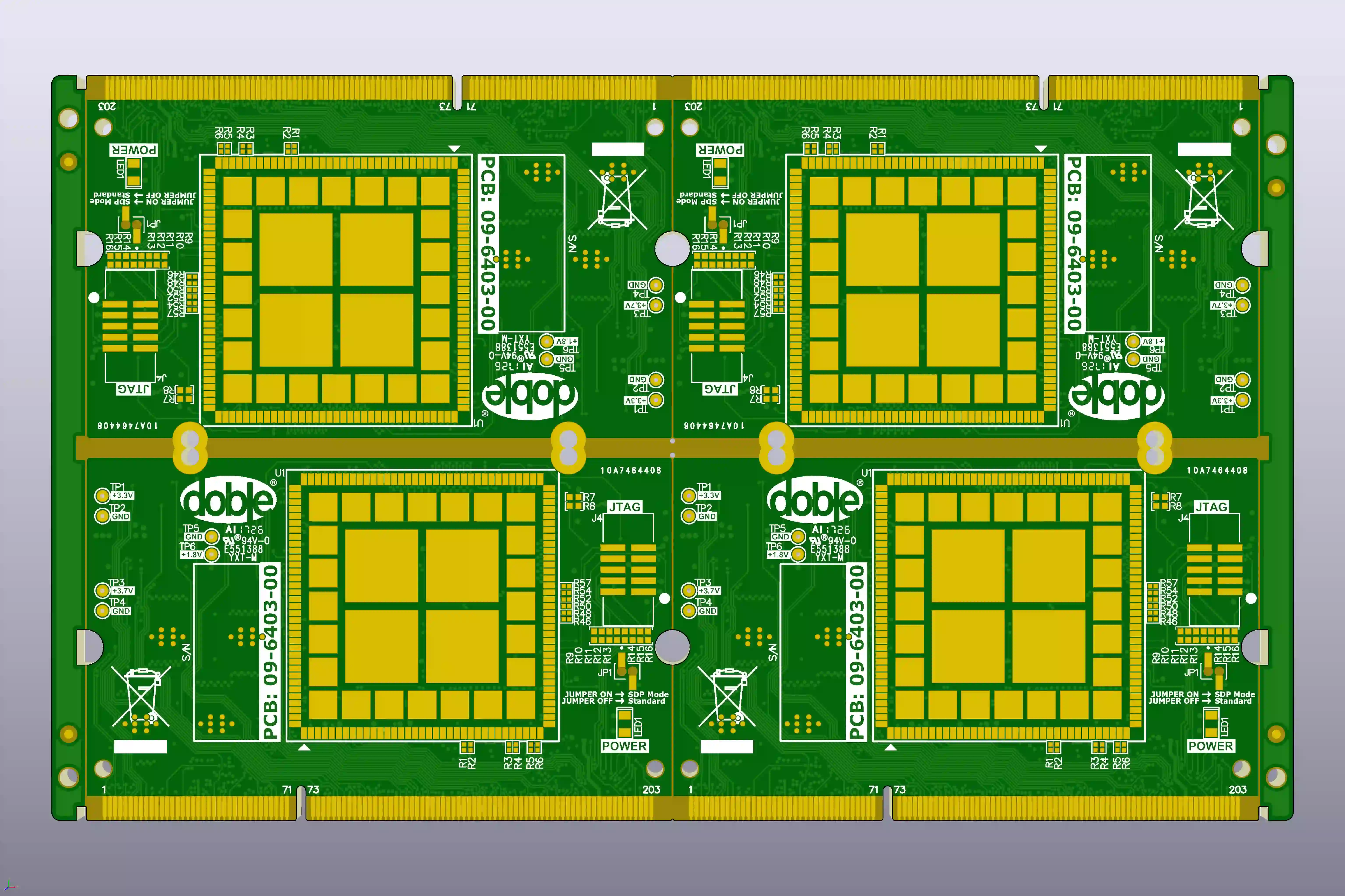
Real 10-layer FR-4 case study: how CAM engineers resolved gold finger bevel clearance, impedance mismatch, tight via spacing and plugging risks to prevent scrap and signal integrity failures.
Real Production Records
| Order ID | PCB Type | Layers | Dimensions | Solder Mask | Surface Finish | Quantity | Action |
|---|---|---|---|---|---|---|---|
| FR4-20260819-043 | FR4 PCB | 10 | 157 x 140 | Blue | ENIG (Immersion Gold) | 100 | View detail |
| FR4-20260818-014 | FR4 PCB | 2 | 110.32 x 173.3 | Green | ENIG (Immersion Gold) | 200 | View detail |
| FR4-20260811-033 | FR4 PCB | 8 | 226.8 x 10⁹ | Green | ENIG (Immersion Gold) | 50 | View detail |


