










Resistor Color Codes: Read Them in Seconds
What This Video Covers
This short walks through the IEC 60062 color-band method used on axial through-hole resistors during prototype builds, incoming inspection, and mixed-technology turnkey PCB assembly. Four-band parts encode two significant digits, a multiplier, and tolerance. Five-band parts add a third digit before the multiplier, which is why brown-black-black-red-gold and brown-black-orange-gold can both read as 10 kΩ ±5%.
The video uses two factory-typical examples: brown-black-orange-gold (10 × 1,000 = 10 kΩ ±5%) and brown-black-black-red-gold (100 × 100 = 10 kΩ ±5%). That distinction matters on FR4 PCB prototypes, industrial control boards, and consumer electronics where a backward read or a 4-band/5-band mix-up puts the wrong value on a pull-up, divider, or current-limit net. After you learn the band order, confirm the part against the BOM before you send a PCB prototype or PCBA quote.
Key Highlights
- Four-band resistors: first two bands = digits, third = multiplier, last = tolerance (gold = ±5%). Brown-black-orange-gold = 10 kΩ ±5%.
- Five-band resistors: first three bands = digits, fourth = multiplier, fifth = tolerance. Brown-black-black-red-gold = 100 × 100 = 10 kΩ ±5%.
- Rule of thumb: four bands give two digits; five bands give three digits—then multiplier, then tolerance.
4-Band vs 5-Band Resistor Color Codes
Through-hole resistors still appear on mixed-technology boards, power stages, connectors, and service-friendly designs. The body is too small for printed text, so IEC 60062 color bands carry value and tolerance. Reading direction is not optional. Start at the end where the digit bands are grouped. Gold or silver is almost always the tolerance band and sits on the right.
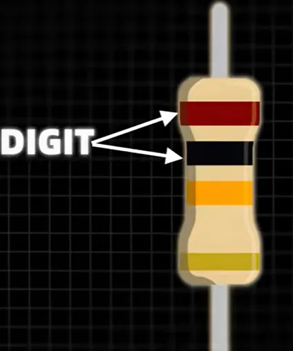
A 4-band code is Digit–Digit–Multiplier–Tolerance. The video's first example is brown (1), black (0), orange (×1,000), gold (±5%) → 10 kΩ ±5%. A 5-band code is Digit–Digit–Digit–Multiplier–Tolerance. The second example is brown (1), black (0), black (0), red (×100), gold (±5%) → 100 × 100 = 10 kΩ ±5%. Same nominal value, different band count. Incoming inspectors who assume "every 10k is four bands" will reject good 5-band stock or accept a wrong 4-band substitute.
On the line, the failure mode is substitution, not theory. A 10 kΩ pull-up swapped for 1 kΩ or 100 kΩ changes rise time, LED current, or ADC divider ratio. Carbon-film 5% parts (gold) and metal-film 1% parts (brown tolerance) can share a similar body size. If the BOM calls for 1% and the kit contains 5% 4-band parts, color reading is the first filter before a meter check.
| Band count | Band 1 | Band 2 | Band 3 | Band 4 | Band 5 | Video example |
|---|---|---|---|---|---|---|
| 4-band | 1st digit | 2nd digit | Multiplier | Tolerance | — | Brown-Black-Orange-Gold = 10 kΩ ±5% |
| 5-band | 1st digit | 2nd digit | 3rd digit | Multiplier | Tolerance | Brown-Black-Black-Red-Gold = 10 kΩ ±5% |
| 6-band (precision) | 1st digit | 2nd digit | 3rd digit | Multiplier | Tolerance | Tempco (ppm/°C) — not in this short |
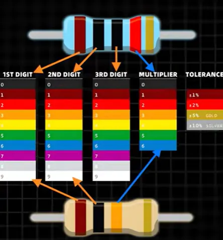
Standard Color-to-Value Map Used in Incoming Inspection
Memorize digits first. Black through white map 0–9 in rainbow order after brown: black 0, brown 1, red 2, orange 3, yellow 4, green 5, blue 6, violet 7, gray 8, white 9. Multiplier uses the same colors as powers of ten, plus gold (×0.1) and silver (×0.01). Tolerance is a separate column: brown ±1%, red ±2%, gold ±5%, silver ±10%, none ±20%.
Factory lighting and conformal coating change perceived color. Brown vs red and orange vs yellow are the most common mix-ups under yellow shop lighting. A second check is band spacing: the gap before the tolerance band is usually wider than the gaps between digit bands. If both ends look similar, compute both directions and keep the value that exists in the E24/E96 series and the BOM.
Do not use color bands as the only acceptance method on a production kit. Measure a sample with a calibrated meter after the part has cooled. A 10 kΩ ±5% part must fall between 9.5 kΩ and 10.5 kΩ. Out-of-tolerance parts that still "look like 10k" are a supplier-quality issue, not a decoding issue.
| Color | Digit | Multiplier | Tolerance |
|---|---|---|---|
| Black | 0 | ×1 | — |
| Brown | 1 | ×10 | ±1% |
| Red | 2 | ×100 | ±2% |
| Orange | 3 | ×1,000 | — |
| Yellow | 4 | ×10,000 | — |
| Green | 5 | ×100,000 | ±0.5% |
| Blue | 6 | ×1,000,000 | ±0.25% |
| Violet | 7 | ×10,000,000 | ±0.1% |
| Gray | 8 | ×100,000,000 | ±0.05% |
| White | 9 | ×1,000,000,000 | — |
| Gold | — | ×0.1 | ±5% |
| Silver | — | ×0.01 | ±10% |
Why Misreading Bands Causes Assembly and Rework Failures
Most field failures tied to "wrong resistor" are not mysterious. They start at kitting. A 4-band 1 kΩ (brown-black-red-gold) and a 4-band 10 kΩ (brown-black-orange-gold) differ by one band. Under magnification they look similar. Placed on a reset pull-up, the 1 kΩ part can hold a rail in the wrong state or overload a GPIO. Placed in a current-limit path, the 10× error can overheat an LED or a driver.
Wave-solder and selective-solder lines do not catch value errors. AOI can read polarity and presence; it rarely decodes color bands reliably across vendors. That is why first-article inspection still uses a human plus a meter on through-hole kits. After coating, bands are harder to read, so the window for correction is incoming QA and first-article—not field return.
DFM recommendation: prefer SMD chip resistors on new designs unless the product needs hand service, high pulse energy, or connector-adjacent through-hole parts. When through-hole is required, lock the BOM to a single band style (4-band 5% or 5-band 1%) per value, print the value next to the reference designator on silkscreen where space allows, and include the manufacturer part number in the AVL so purchasing cannot silently swap a 5% body for a 1% body.
Through-Hole Color Bands vs SMD Numeric Codes
Modern SMT boards use chip resistors marked 103, 1002, or EIA-96 codes such as 01C—not color bands. A 103 SMD part is 10 kΩ, the same nominal value as the video's axial examples. Confusing the two systems on a mixed board is a common technician error during rework: reading a chip as if it were a 3-band color code, or assuming an unmarked 0402 is open.
For new PCB mass production and turnkey assembly, specify package, tolerance, TCR, and power in the AVL. Color-band skill remains useful for repair, education kits, power resistors, and older industrial controllers. It is not a substitute for a placement file and a golden sample.
FAQ
Q1: Can a 4-band and a 5-band resistor both be 10 kΩ ±5%?
A1: Yes. Four-band brown-black-orange-gold is 10 × 1,000. Five-band brown-black-black-red-gold is 100 × 100. Same nominal value and gold tolerance. Do not reject one style if the BOM allows both, but do not mix 1% and 5% parts on analog nets.
Q2: How do I know which end is the first band on a through-hole resistor?
A2: Start at the grouped digit bands. Gold or silver is normally the last (tolerance) band. A wider gap usually sits before tolerance. If both orientations are plausible, keep the value that matches an E-series number and the BOM, then confirm with a meter.
Q3: Should production PCBA lines rely on color-band reading instead of a meter?
A3: No. Use color bands for fast incoming sort and first-article screening. Accept parts against the BOM tolerance window with a calibrated ohmmeter. AOI does not reliably decode painted bands across vendors and lighting.
Q4: When should an OEM drop axial color-band resistors for SMD chips?
A4: Drop them when density, pick-and-place yield, and reel logistics matter more than hand service. Keep through-hole for high-energy, high-voltage, or field-replaceable parts. New consumer, IoT, and most industrial boards should default to 0402/0603/0805 chips with numeric codes.
Q5: Does gold tolerance (±5%) meet analog divider or timing requirements?
A5: Often no. A 10 kΩ ±5% divider can shift 5% on each leg. Precision sense, ADC references, and RC timing usually need 1% (brown) or better plus a defined TCR. Specify that in the AVL; do not assume a gold-band 10k is interchangeable with a 1% 10k.
The colors tell you everything.
Start with the first two bands.
They give you the first two digits.
Brown means 1.
Black means 0.
The third band is the multiplier.
Orange means ×1,000.
So, 10 × 1,000 gives you 10 kilo-ohms.
The last band shows the tolerance.
Gold means ±5%.
Now look at this resistor.
This is a five-band resistor.
The first three bands give you three digits.
Brown, black, black:
that's 100.
Red is the multiplier: ×100.
Gold means ±5%.
So, 100 × 100 gives you 10 kilo-ohms ±5%.
Remember:
four bands give you two digits,
while five bands give you three.
Then comes the multiplier,and finally, the tolerance.





