










What Is a Copper Core PCB? Heavy Power and Heat Management Explained
WHAT THIS VIDEO COVERS
This video explains copper core PCBs — specialized boards designed for extreme power and thermal demands that standard FR4 or even aluminum PCBs cannot handle effectively.
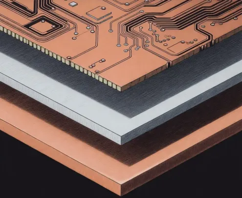
Unlike conventional PCBs, a copper core PCB features a robust three-layer construction: copper circuitry on top for signals and power distribution, a thin dielectric layer for electrical insulation, and a thick solid copper base that acts as both a heat spreader and high-current carrier. This structure enables rapid and even heat dissipation while supporting very high current loads without excessive temperature rise.
Copper core PCBs are typically chosen for power modules, motor drives, industrial converters, and other high-power density applications where reliability under heavy load is non-negotiable. While they come with higher material and manufacturing costs, their performance justifies the investment in mission-critical designs.
The video highlights when to specify copper core construction versus other thermal solutions like aluminum PCBs or heavy copper designs.
Request a custom instant PCB quote for your high-power project. Explore our dedicated copper core PCB capabilities or heavy copper PCB options. For complete solutions, see our power supply PCB and PCB assembly services.
KEY HIGHLIGHTS
- Copper core PCBs consist of top copper circuitry, a thin dielectric layer, and a thick solid copper base for superior heat spreading and high-current handling.
- The thick copper core rapidly dissipates heat evenly, preventing hotspots in high-power circuits.
- Best suited for power modules, motor drives, and industrial converters where extreme thermal and electrical performance is required.
Copper Core PCB Construction and Three-Layer Design
A copper core PCB integrates a solid copper substrate, typically 0.5 mm to several millimeters thick, as the primary structural and thermal element. The top layer carries standard copper traces for circuitry, separated by a thin, thermally conductive dielectric (often 50–200 μm) that provides electrical isolation while allowing efficient heat transfer from components to the base.
In production, the thick copper base requires specialized lamination and machining processes. Unlike standard FR4 panels, copper cores demand precise control during pressing to avoid delamination or voids in the dielectric. Panelization must account for the material's higher density and thermal expansion characteristics to maintain flatness.
Common manufacturing variations include different copper base thicknesses tailored to power dissipation needs. Thicker bases (e.g., 2–3 mm) excel in applications exceeding 50–100W dissipation but increase overall board weight and machining complexity.
Thermal Performance Advantages Over FR4 and Aluminum PCBs
Copper offers approximately 400 W/m·K thermal conductivity, significantly outperforming aluminum (~200 W/m·K) and FR4 (~0.3–1 W/m·K). This enables superior lateral and through-plane heat spreading, reducing junction temperatures in high-current paths and minimizing the need for additional heatsinks.
In real production scenarios, copper core designs prevent hotspots that commonly lead to solder joint fatigue or component derating in aluminum-based boards under sustained high loads. The material's higher mechanical strength also improves vibration resistance, critical for automotive and industrial environments.
However, the denser copper base results in heavier boards and requires careful thermal expansion matching during design to avoid stress on components or vias during temperature cycling.
Key Applications in High-Power Electronics
Copper core PCBs are preferred in power modules, motor drives, industrial converters, DC-DC converters, solar inverters, and EV battery management systems where high current density and reliable operation under thermal stress are mandatory.
In motor drive applications, the core handles bus currents effectively while dissipating IGBT or MOSFET heat. For power supplies, it supports compact designs with minimal external cooling, improving overall system efficiency and longevity.
Manufacturing case studies often show copper core solutions reducing failure rates in high-power density layouts compared to alternatives, particularly where repeated thermal cycling occurs.
DFM Guidelines and Manufacturing Challenges for Copper Core PCBs
DFM best practices include specifying appropriate dielectric thickness for voltage isolation, optimizing trace widths and via placement for current carrying, and incorporating thermal reliefs or filled vias where needed. Annular ring sizes should be enlarged to accommodate drilling challenges in thick copper.
Common production issues involve burr formation during drilling, tool wear on routing equipment, and potential warpage if lamination parameters are not tightly controlled. V-scoring and depanelization require diamond tooling or adjusted parameters due to material hardness.
Failure modes such as dielectric breakdown under high voltage or poor thermal interface contact often stem from inadequate DFM review. Early engagement with the fabricator for stackup validation and impedance (if multilayer) is recommended.
Parameter Comparison
| Parameter | Copper Core PCB | Aluminum PCB | Standard FR4 (Heavy Copper) |
|---|---|---|---|
| Thermal Conductivity | ~400 W/m·K | ~200 W/m·K | ~0.3–1 W/m·K |
| Current Capacity | Excellent (thick base) | Good | Moderate (trace dependent) |
| Weight | High | Medium | Low |
| Cost | Higher | Medium | Lower |
| Best For | Extreme power/thermal loads | LEDs, moderate power | General electronics |
Copper Core PCB Selection Guide and Cost Considerations
Selection depends on power dissipation levels, environmental conditions, and budget. Copper core excels where aluminum falls short in sustained high-current scenarios or where maximum reliability justifies the premium.
Manufacturing costs rise due to material price, specialized processing, and lower panel utilization. Designers should balance these against reduced cooling requirements and improved MTBF in the final assembly.
FAQ
Q1: What is the difference between copper core PCB and aluminum PCB?
A1: Copper core PCBs offer better thermal conductivity and higher current-carrying capacity than aluminum PCBs, making them ideal for very high-power applications, though they are heavier and more expensive.
Q2: When should you use a copper core PCB?
A2: Use copper core PCBs in high-current, high-power designs such as power supplies, motor drives, and industrial converters where superior heat dissipation and reliability under heavy load are essential.
Q3: Why are copper core PCBs more expensive?
A3: They require thicker solid copper bases and specialized manufacturing processes, increasing material and fabrication costs compared to standard or aluminum-based boards.
Q4: How does copper core PCB compare to heavy copper FR4 in high-power applications?
A4: Copper core provides a dedicated thick base for superior bulk heat spreading and current handling, while heavy copper FR4 relies on thicker traces and planes. Copper core is often preferred for the highest power densities, though heavy copper offers more multilayer flexibility at potentially lower cost for moderate demands.
Q5: What are common failure modes in improperly designed copper core PCBs?
A5: Failures include dielectric breakdown from voltage stress, hotspots due to poor component placement, and mechanical issues from inadequate burr control or warpage. Thorough DFM review and prototype validation mitigate these risks in production.
Why do some power boards look unusually thick and heavy?
That's often a copper core PCB.
Unlike standard PCBs, copper core PCBs are built for extreme conditions.
High current. High power. And serious heat.
A copper core PCB isn't just copper traces on fiberglass.
It has three key parts.
Copper traces on top for signals and power.
A thin dielectric layer in the middle for electrical insulation.
And a solid copper base underneath.
This thick copper base spreads heat fast and evenly.
It also handles very high current without overheating.
That's why copper core PCBs are common in power modules, motor drives, and industrial converters.
The trade-off is higher material and manufacturing demands.
Copper core PCBs are chosen for performance, not convenience.
So engineers don't use them everywhere —only when power density and reliability really matter.





