










From Prototype to Walkie-Talkie: Building an ESP32 Custom PCB
Key Moment
Project Background
Makers and electronics engineers constantly seek practical, infrastructure-free wireless voice solutions that feel like real radios rather than temporary bench experiments. Tech Talkies set out to answer a clear question: could two compact XIAO ESP32-S3 Sense boards deliver real-time, push-to-talk voice communication without a router, without an app, and without constant pairing? The answer became a pair of low-latency walkie-talkies that stream audio peer-to-peer via ESP-NOW on 2.4 GHz, capture sound with the onboard PDM microphone, and play it cleanly through a MAX98357A amplifier and 23 mm speaker.
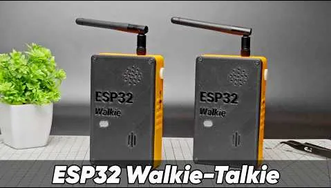
The creator's ambition went beyond proving a concept on jumper wires. The goal was a pair of consistent, field-ready handhelds that could survive outdoor use, battery swaps, and closed 3D-printed enclosures. That shift from working prototype to reliable product made professional PCB design and manufacturing essential. A custom 30 × 70 mm board became the mechanical and electrical foundation that turned two identical modules into polished tools.
In the broader market of rapid PCB prototyping and wireless audio projects, this build highlights a common need among B2B engineers and makers: converting functional ESP-NOW or I2S prototypes into production-ready form factors quickly and cost-effectively.
What This Video Covers
This video walks through the complete journey of building and refining an ESP32-based wireless walkie-talkie pair. It begins with the core concept of router-free, real-time audio using ESP-NOW, then demonstrates hardware assembly around the XIAO ESP32-S3 Sense, MAX98357A amplifier, external 3 dB antenna, PTT button, slide switch, and removable 18650 battery.
Firmware details include automatic role assignment via MAC address comparison, 16 kHz audio sampling packaged into 128-sample packets, a thread-safe ring buffer that isolates Wi-Fi callbacks from the I2S DMA engine, software gain with hard clipping protection, and synthesised status tones (key-up tone, roger beep, link-check pings every 30 seconds).
The second half focuses on the transition to a custom 3 × 7 cm PCB, layout priorities for clean I2S and RF performance, mechanical fit inside the 3D-printed case, outdoor range testing beyond 200 m, and the practical value of professional manufacturing consistency. Viewers see both the working system in action and the engineering decisions that make the finished handhelds feel radio-like rather than experimental.
Project Highlights and Key Features
- Peer-to-peer ESP-NOW audio streaming at 16 kHz with almost no perceptible delay and no external infrastructure required.
- Onboard PDM microphone on each XIAO ESP32-S3 Sense eliminates extra wiring and keeps the design compact.
- Thread-safe ring buffer plus software gain limiting prevent pops, drop-outs, and saturation even under varying link conditions.
- Automatic Device 1 / Device 2 role assignment at power-up based on stored MAC addresses, plus polished status tones that give the pair a professional radio character.
- External 3 dB whip antenna and continuous ground plane deliver usable outdoor range beyond 200 m and solid multi-room indoor coverage.
- Compact 30 × 70 mm 2-layer FR-4 board (1.6 mm, 1 oz copper, HASL or ENIG) integrates the XIAO module, MAX98357A, PTT button, power slide switch, and antenna connector while maintaining short I2S runs and a clear antenna keep-out zone.
- Removable 18650 battery shield with dedicated slide switch that truly breaks the battery rail, preventing slow drain.
- Identical firmware and matched hardware produce two units that behave almost the same—critical for consistent field performance.
Challenges Encountered During Development
Moving from an open-bench prototype to a closed handheld enclosure surfaces several practical issues that pure firmware success cannot solve. Audio integrity is the first: ESP-NOW receive callbacks run outside the main loop, so without a properly protected producer-consumer ring buffer the I2S DMA engine can process incomplete packets and produce audible pops or drop-outs.
RF performance is equally sensitive. The XIAO's onboard antenna works on the desk, yet outdoor range improves dramatically only when an external 3 dB whip is used and a copper-free keep-out zone of at least 5 mm is maintained around the connector. Nearby ground pours or battery pads detune the radiator and reduce range.
Mechanical and power constraints appear once the case closes. The battery shield's switch typically interrupts only the USB rail, so a separate slide switch on the battery positive is required. Component heights must be checked against the 3D-printed enclosure STEP model early; otherwise tidy bench wiring becomes impossible to close. Supply noise from the MAX98357A can also enter the audio path once microphone gain is raised, demanding local decoupling (100 nF + 10 µF) right at the amplifier pins and a continuous ground under the audio section.
Finally, small-batch manufacturing variation—differences in copper weight, soldermask registration, or hole plating—can create unit-to-unit differences in audio quality or RF performance that are difficult to debug after assembly. Pad sizes that are too tight for comfortable hand soldering or insufficient annular rings on the PTT button risk cracked joints after repeated outdoor presses. All of these challenges must be anticipated during layout if the finished boards are to support the firmware's strengths rather than fight packaging constraints.
How AIVON PCB Helps
Once the firmware and audio path were proven, the remaining task was to produce two identical boards that could be assembled once, fitted into the cases, and trusted for repeated outdoor use. AIVON PCB's rapid PCB manufacturing and expert DFM review made that transition reliable and efficient.
AIVON produced the 3 × 7 cm boards with consistent copper weight, soldermask registration, and hole plating across the small batch. That consistency eliminated the unit-to-unit differences that plague hand-assembled prototypes, so the two finished walkie-talkies behaved almost identically in audio quality and RF range. The continuous ground plane delivered the quiet reference the I2S lines needed, while short, direct routing from the XIAO pins to the MAX98357A kept digital edges clean.
AIVON's engineering feedback caught practical details before fabrication: footprints that were slightly tight for hand soldering were enlarged, and the PTT button pads received more generous annular rings so they would survive hundreds of presses without cracking. Guidance on the antenna keep-out zone and ground-plane continuity further refined the layout, helping the external 3 dB whip achieve the measured outdoor range beyond 200 m. Local decoupling recommendations and verification of component heights against the case model prevented last-minute mechanical surprises.
Because the boards arrived ready for clean assembly, the creator could focus on final mechanical fit and field testing rather than troubleshooting manufacturing variation. The solid ground and proper decoupling also allowed slightly higher software gain without introducing harshness, improving the overall listening experience. AIVON's one-stop combination of fast-turn PCB prototyping, thorough DFM analysis, high-quality fabrication, and reliable delivery turned a working concept into a pair of polished, field-ready handhelds.
Conclusion
Tech Talkies began with two small modules and a clear intention: deliver practical peer-to-peer voice without external infrastructure. The difficult problems—thread-safe audio streaming, automatic role assignment, synthesised status tones, and usable outdoor range—were solved through careful firmware and iterative testing. The cleanly manufactured 3 × 7 cm PCB simply provided those solutions with a mechanical and electrical foundation that could leave the bench and keep performing.
For engineers developing similar wireless-audio or ESP-NOW projects, the same sequence applies: validate the signal path, address real packaging and RF constraints, then manufacture a board that respects continuous ground, short I2S runs, antenna clearance, and adequate pad sizes. The distance from a working prototype to a reliable handheld is shorter than it first appears.
FAQ
Q1: Why is a 2-layer board sufficient for an ESP-NOW + I2S walkie-talkie PCB?
A1: At 16 kHz audio rates and typical ESP-NOW power levels, controlled impedance is unnecessary. A continuous ground plane on a standard 2-layer FR-4 board already provides the quiet reference and short return paths needed for clean I2S and stable RF performance on a compact 30 × 70 mm design.
Q2: How large should the antenna keep-out zone be on a compact handheld PCB?
A2: Leave at least 5 mm of copper-free area under and around the external antenna connector and feed. Copper pours, battery pads, or ground planes closer than this measurably reduce outdoor range by detuning the whip and increasing losses.
Q3: What are the key layout rules for I2S lines next to an ESP32-S3 module?
A3: Keep BCLK, WS, and DIN as short as possible (ideally under 25 mm), route them together as a tight group, and run them over an unbroken ground plane. Avoid vias in these traces when possible and keep them away from the antenna region and switching power nodes to minimise digital noise in the audio path.
Q4: Which surface finish works best for hand-assembly of a small XIAO + MAX98357A board?
A4: HASL is economical and fully adequate for prototype quantities. ENIG offers flatter pads that make fine-pitch XIAO soldering slightly easier and improves long-term corrosion resistance for outdoor use. Either finish works well when pad sizes are confirmed generous enough during DFM review.
Q5: What common DFM issues appear when combining a battery shield, PTT button, and external antenna on a 3 × 7 cm board?
A5: The most frequent problems are insufficient annular rings on the PTT pads (leading to cracked joints after repeated presses), copper too close to the antenna connector, and component heights that collide with the 3D-printed case. Checking maximum component height against the enclosure STEP model and enforcing a clear antenna keep-out during layout prevents these issues before the first boards are ordered.
Can you hear me? Yes, I can hear you more.
I finally made an ESP32 walkie-talkie. It has an external antenna giving it more than 100 m of range or even more. You can easily swap the batteries if you need to out in the field. And it can even charge your phone in an emergency. And let me show you how I built it.
To build this walkie-talkie, we will need the custom 3D printed parts. And for the components, I will be using a Xiao ESP32S3 Sense microcontroller. It is really small and the add-on board has a high quality microphone and most importantly, we can attach an external antenna to it. All this makes it an ideal candidate for this project.
A MAX98357 amplifier and a 23 mm speaker, a 18650 battery shield and a battery for it, a 4 mm push button and a slide switch.
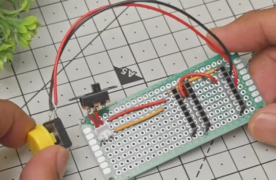
I've made the connections on a 3x7 PCB. The connection diagram link is in the description.
If there is still some gap between the button and the support structure, you can fold a small piece of electrical tape and put it inside the gap.
The on/off switch on the battery shield works only for the USB port. The power pads are always supplying power. That's why we have a separate switch in the circuit.
Before adding the ESP32, we need to upload the code to it. The code link is also in the description. Download and open it using the Arduino IDE. You'll notice that there's a tab called secrets. In this tab, you'll have to paste the MAC addresses of the two ESP32 boards that are going to communicate with each other. For now, this program is designed to run on two paired walkie-talkies at a time, and we will update this in future builds.
To find the MAC address of any ESP32, upload the MAC address program that is included in the GitHub repo and open the serial monitor. Now you can see the MAC address of this ESP32. Do this for both the boards and copy paste them in the secrets tab of our main program. Then upload the main program to both the ESP32.
And if you need a custom PCB for a project, Aivon is a one-stop PCB manufacturing and assembly service. So you can go from design to fully assembled board without juggling multiple vendors. Ordering is also pretty straightforward. You can go to their website, upload your Gerber files, select your board specs like thickness, layers, and quantity, and you'll get an instant quote. From there, you can place your order, track the progress online, and they handle the rest, including fabrication and even assembly if needed. They support everything from quick prototypes to full production runs. If you want to try it out, I have left the links in the description. Go check them out.
I've printed this part with transparent PLA, but white should also work and it should fit nicely in there. But if it is a bit loose for you, just add a little bit of super glue to the sides and it should fit right on there.
I have already made my second unit earlier. Let's test them out. I have my friend here with the second walkie-talkie.
Can you hear me? Yes, I can hear you.
Okay, stop. I can hear you still. I can hear you.
I think he's about 200 m away now. We can still hear the ping beep. It keeps beeping as long as we are connected to each other.
Can you hear me? Over. Over.
Can you hear me? Over. Yes, I can hear you.
I think this is enough. I think that's far enough. My friend is all the way over there.
Hello and we are talking over ESP32. You can come back over.
So there you go. That's our personal ESP32 walkie-talkie. They are easy to build and require no licensing as they work on Wi-Fi rather than traditional radio frequencies which do require licensing.
Comment if you have any questions and keep making.





