










Desk Buddy V2: Building a Compact ESP32 Robot with a Custom PCB
Key Moment
- 0:00 Introduction – Desk Buddy V1 to V2
- 0:34 Redesigning with 3D Printed Parts
- 0:43 Components Overview (XIAO ESP32S3, Motors, Sensors)
- 1:26 PCB Assembly & Wiring
- 2:05 AIVON PCB Sponsorship
- 6:10 Demo – Exploring, Obstacle & Edge Avoidance
- 6:40 Phone Control & Cute Sounds
- 7:09 Motor Torque Problem Explained
- 7:33 Future Plans (Servo Redesign) & Code Status
- 8:03 Call for Suggestions & Outro
Project Background
Desk companions that roll across a work surface, detect edges, react to nearby objects, and display animated expressions have become a favorite category among makers. The original Desk Buddy captured exactly that playful spirit and quickly generated requests for more capability. Viewers wanted genuine autonomy—obstacle and edge detection, phone-based control, audible feedback, and a cleaner power system—while still fitting everything inside a fully 3D-printed chassis small enough to live on a crowded desk.
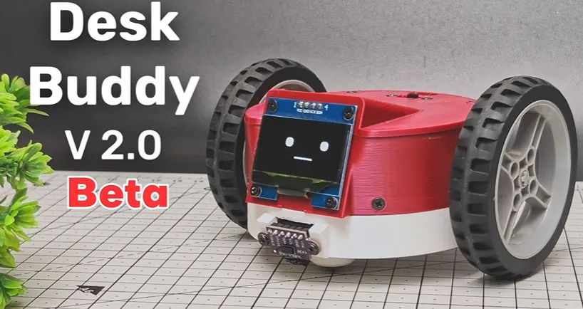
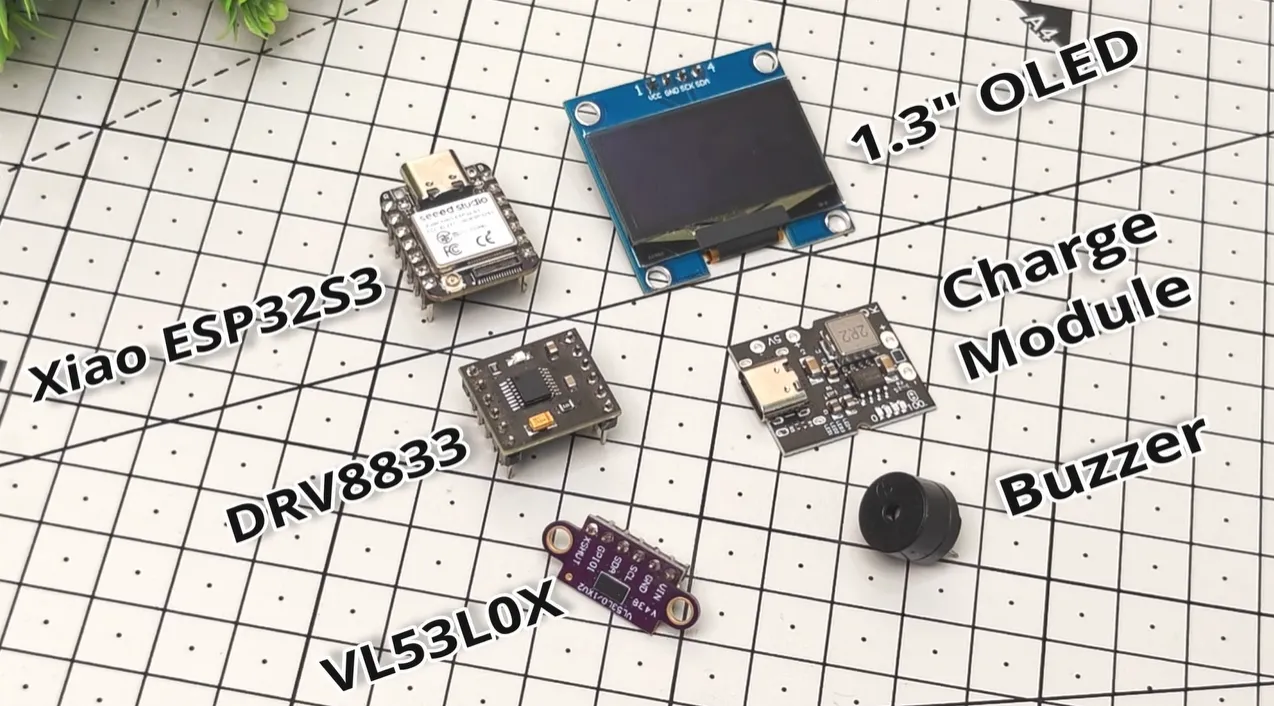
Tech Talkies answered with Desk Buddy V2. The brain moved to the more capable Seeed Studio XIAO ESP32S3. Dual 90-degree N20 gear motors and LEGO wheels provided the drivetrain. A VL53L0X Time-of-Flight sensor handled distance sensing, a 1.3-inch OLED kept the familiar face, a buzzer added personality, and a LiPo battery paired with a USB-C charger and boost converter managed power. All of these modules had to coexist in a footprint only a few centimeters across. Hand-wired prototypes quickly became unreliable under motor load and vibration. A compact, purpose-designed carrier board was no longer optional; it became the foundation that would let the robot actually leave the workbench.
The full story of that transition is captured in the KOL video and expanded in the detailed project article Custom PCB Design Behind Desk Buddy V2 – From Sketch to Rolling Companion.
What This Video Covers
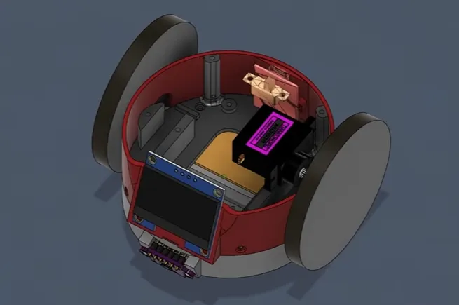
The video walks through the complete V2 upgrade path. It opens with a quick reminder of the original Desk Buddy, then introduces the new mechanical and electrical architecture. Viewers see the fully 3D-printed body, custom motor adapters, front caster, and the dual N20 + LEGO-wheel drivetrain. On the electronics side the video highlights the XIAO ESP32S3, DRV8833 motor driver, VL53L0X ToF sensor, OLED, buzzer, and the integrated LiPo power path.
A key sequence shows the beta robot exploring a real desk: continuous ToF ranging, edge detection that stops or turns the robot, obstacle avoidance, phone takeover, and the animated expressions plus buzzer sounds that give the machine personality. The creator is transparent about remaining limitations—chiefly the insufficient torque of the current motors—and outlines the planned servo-based drivetrain redesign. Throughout, the 6 × 4 cm custom PCB is shown as the quiet enabler that replaced point-to-point wiring and kept sensing and control stable even while the motors ran.
Project Highlights and Key Features
- Compact 2-layer FR-4 carrier board (approximately 6 × 4 cm, 1.0 mm thick) that consolidates MCU, motor driver, sensors, and power management.
- Seeed Studio XIAO ESP32S3 providing Wi-Fi phone control, ample GPIO, and sufficient processing for real-time ToF and display updates.
- VL53L0X Time-of-Flight sensor delivering continuous obstacle and table-edge detection.
- DRV8833 dual motor driver with dedicated power pours and local bulk + high-frequency decoupling to limit voltage sag.
- 1.3-inch OLED and buzzer sharing clean, short I2C and GPIO routes kept away from motor current paths.
- ENIG surface finish chosen for reliable soldering on the fine-pitch XIAO stamp-hole footprint and the motor-driver package.
- Solid ground plane under sensitive sections combined with star-point or ferrite isolation between motor power and signal ground.
- Antenna keep-out zone of 5–8 mm ensuring reliable Wi-Fi for phone control.
- Fully 3D-printed chassis with custom motor adapters and a front caster that accepts the thin board without stress.
- Headroom left in the layout so a future continuous-rotation servo drivetrain can reuse the same electrical foundation.
Challenges Encountered During Development
Moving from a wired prototype to a mobile desk robot exposed several classic problems. The 90-degree N20 gearboxes simply lacked the torque needed once battery, sensors, and printed body were added. At the gentle speeds required for desk travel the motors stalled; at full power the robot raced and still struggled with surface variations. That mechanical shortfall is openly acknowledged as the reason a servo redesign is already planned.
Electrically, earlier point-to-point versions suffered voltage dips and I2C glitches whenever the motors started. Motor current and sensitive sensor lines shared the same ground return, and decoupling was insufficient. Fitting connectors so they could be reached after the chassis was closed, choosing pad and via sizes that would survive hand or small-batch assembly, and keeping the board thin enough (1.0 mm) for the printed mounts all required careful iteration. Any layout that ignored antenna clearance risked unreliable phone control. Timeline pressure was real: the mechanical design was still evolving, so the PCB had to be both correct the first time and flexible enough for the next mechanical leap.
How AIVON PCB Helps
AIVON's rapid PCB manufacturing and free engineering review turned those risks into a stable platform. An instant online quote gave Tech Talkies clear cost and lead-time visibility. The subsequent free DFM analysis flagged borderline pad sizes, suboptimal via placement that would have lowered yield, and connector orientations that would have made final assembly awkward inside the tight 3D-printed enclosure. Minor adjustments recommended by AIVON engineers improved both manufacturability and long-term reliability without forcing a complete redesign.
The delivered boards used the specified 1.0 mm thickness and ENIG finish, ensuring consistent solder joints on the XIAO's fine-pitch footprint and the DRV8833. Separate motor-power pours, a continuous signal ground plane, and short controlled I2C routes kept the VL53L0X and OLED stable under load—the exact noise isolation that earlier wired versions lacked. Because the boards arrived quickly and correctly the first time, development effort could stay focused on firmware and the mechanical beta rather than chasing manufacturing defects. AIVON's combination of fast-turn production, expert DFM feedback, and prototype-friendly quality made the compact carrier the reliable electrical foundation that now supports sensing, expression, and phone control while leaving clear headroom for the planned servo upgrade.
Conclusion
Desk Buddy V2 demonstrates a practical truth for any small battery-powered robot or sensor platform: get the PCB right early. Clean power distribution, noise isolation, manufacturable layout, and a thickness that matches the mechanical design convert an ambitious collection of modules into a coherent, repeatable prototype that can actually live on a desk. The electrical system is already solid; the next mechanical iteration can build on it rather than starting over.
FAQ
Q1: Why choose a 2-layer PCB for an ESP32 robot that includes motors and a ToF sensor?
A1: A well-planned 2-layer board with solid ground and separated motor-power pours is normally sufficient at this size and switching speed. Four layers add cost and thickness a tiny desk robot does not need; layout discipline delivers the required noise performance more economically.
Q2: How can motor noise be kept from corrupting VL53L0X or OLED readings on a compact board?
A2: Route motor current on dedicated pours, place bulk and high-frequency decoupling directly at the DRV8833 and MCU, keep I2C traces short and distant from motor paths, and consider a small series resistor or ferrite bead on the sensor lines.
Q3: Is 1.0 mm board thickness adequate for a mobile robot?
A3: Yes, provided the PCB is fully supported by the 3D-printed chassis. The thin profile reduces weight and eases fit; mechanical loads should be carried by mounting holes and standoffs, not by the board itself.
Q4: Why select ENIG rather than HASL for this type of prototype?
A4: ENIG produces flatter, more consistent pads that improve soldering reliability on fine-pitch footprints such as the XIAO ESP32S3 and the motor-driver package, and it tolerates multiple reflow or hand-solder cycles better during iterative development.
Q5: What is the most common power-related failure in small ESP32 robot PCBs?
A5: Voltage sag when the motors start. Always locate bulk capacitance next to the motor driver and local decoupling at the MCU; a boost converter helps maintain the regulated rail under sudden load.
A while back, I built this tiny desk robot. A little buddy that roams around your desk, reacts when you pet it, and just hangs out with you while you work.
A lot of you really liked the idea, but the biggest request after the video was this — to make a better version. So, this is Desk Buddy version two beta. You'll understand why I call this a beta version if you watch till the end of the video.
This time I have redesigned it from the ground up using new 3D printed parts.
The brain of the robot is the Seeed Studio Xiao ESP32S3 along with a DRV8833 motor driver, a time-of-flight sensor, a buzzer, a 1.3 inch OLED display, and a type-C charger module.
I am using these 90° N20 geared motors and the bot runs on a LiPo battery.
For the movement, I'm using these LEGO compatible wheels and N20 motor adapters along with a mini caster wheel for the front and a 6x4 cm PCB for the connections.
The connection diagram link is in the description. I've also included a table of detailed pin numbers and where to connect them.
And if you need custom PCBs for projects like these, Aivon provides a structured solution for prototyping and production. For new users, the platform includes up to $60 in welcome credits along with a free engineering review. This includes $30 in manufacturing credit, $30 for shipping, and the free engineering review itself. With this, you can do a lot of things like PCB prototyping, making PCBA orders, or even engineering driven jobs. You simply have to sign up and verify your account and you can start uploading your design and start placing orders.
Once on, the bot starts exploring its desk. It can avoid obstacles, will even try not to fall off the edge. It can also be controlled using a mobile phone. It also makes cute noises once in a while.
It works, but I ran into a huge problem. Apparently, the 90° N20 motors have a very low torque. They can barely move the robot even at full speeds. And that is too fast for a desk robot. At lower speeds, it just stalls. Even at full speeds, it needed a nudge here and there.
So, mechanically, this still needs more work. I'm currently considering redesigning the drive system completely, possibly using servo motors instead. Because of that, the code for this version will not be public yet. I want to first arrive at a more stable and reproducible design before releasing the files and software. But I still wanted to show you the progress so far because I think the concept has a lot of potential. And I'm spending a lot of hours designing this little guy.
So any support would be appreciated. And as always, if you have suggestions for improving the robot, especially for movement and driving design, let me know in the comments.





