There's something irresistible about a little robot that lives on your desk, rolls around, avoids the edge, and shows you a cheeky face on its OLED. That's exactly what Tech Talkies delivered with the original Desk Buddy. Viewers loved it and asked for more. So the creator went back to the workbench and built Desk Buddy V2.
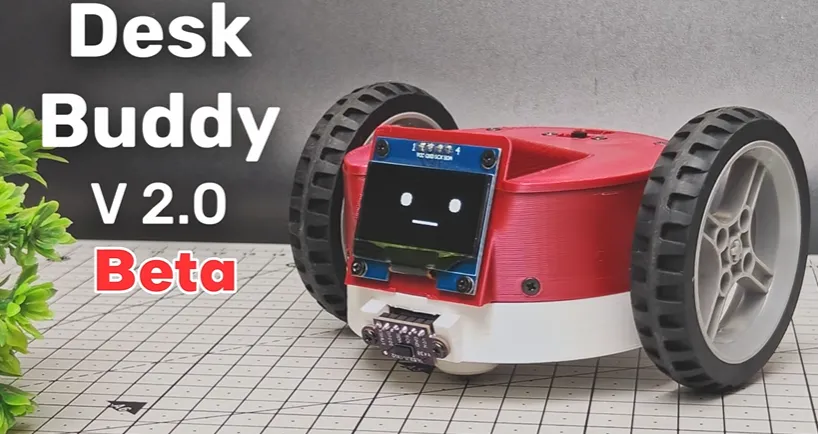
The goal was clear: keep the playful personality, but give the robot real autonomy. Tech Talkies wanted obstacle and edge detection with a Time-of-Flight sensor, phone control, louder expressions via a buzzer, fully 3D-printed body parts, and smoother power management around a LiPo battery. The brain jumped from an earlier ESP32 to the more capable Seeed Studio XIAO ESP32S3. Dual 90-degree N20 gear motors and LEGO wheels completed the drivetrain.
All of that capability had to fit into a tiny footprint without turning into a rat's nest of wires. That is where solid PCB design and manufacturing stop being optional and become the foundation of the whole project.
Watching the Upgraded Robot Explore a Real Desk
Watching the V2 prototype explore a desk is pure maker joy. The robot rolls forward, the VL53L0X ToF sensor constantly checks for obstacles and table edges, and the XIAO ESP32S3 reacts in real time. When it detects a drop-off it stops or turns. When it sees something in its path it changes direction. The 1.3-inch OLED keeps the familiar animated expressions, while the buzzer adds little sound effects that make the robot feel present rather than silent.
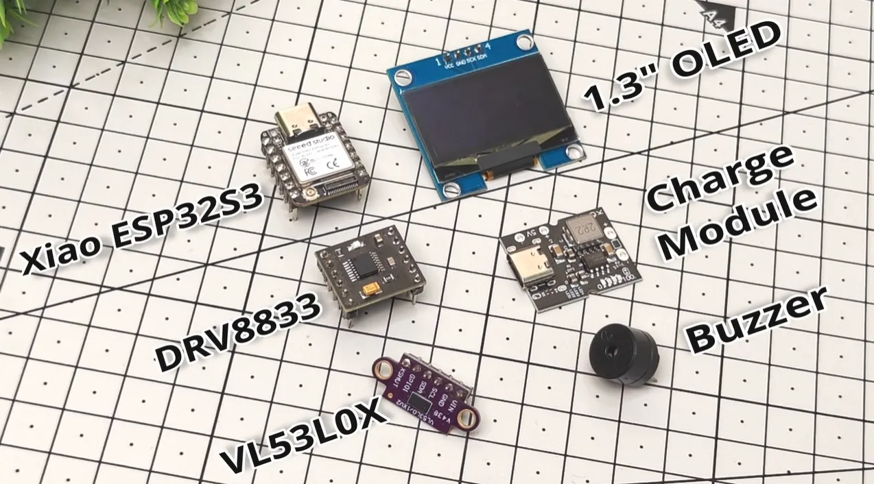
Phone control lets you take over when you want. The dual N20 motors and LEGO wheels give it a playful rolling gait. A USB-C charging module and boost converter keep the LiPo happy and supply clean power to the electronics. Everything is housed in fully 3D-printed parts that the creator designed from scratch, including custom motor adapters and a front caster.
Figure: Components: dual N20 motors, LEGO wheels and 3D parts
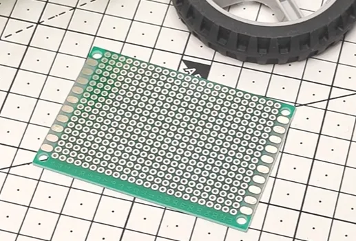
The electrical heart is a compact custom PCB, roughly 6 × 4 cm, that replaces the messy point-to-point wiring of earlier prototypes. The XIAO ESP32S3 sits on it (or is interfaced via its stamp-hole footprint), the DRV8833 motor driver is nearby, and the ToF, OLED, and buzzer share clean I2C and GPIO routes. Power management components sit where they can deliver current to the motors without starving the MCU.
It is still openly called a beta. The 90-degree N20 motors lack the torque needed for consistent movement on a real desk surface, especially at lower speeds where the robot should creep rather than race. Full-speed runs are too fast for a desk companion; partial speeds simply stall. Tech Talkies has already said the drivetrain will be redesigned, possibly with continuous-rotation servos. That honesty is refreshing. The electrical system, however, is already solid enough to support the next mechanical iteration.
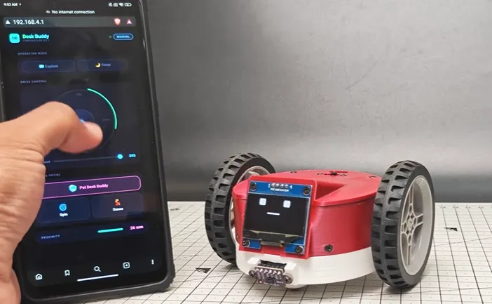
The "wow" moments come from the sensing and the personality. Seeing the robot stop itself at the edge of the desk or react to a hand waving in front of the ToF sensor feels like the project has stepped up from a cute demo to a real companion. The compact board is what made packing all those functions into the small chassis practical.
DFM Checklist for Compact Mobile Desk Robots
|
Check Item |
Why It Matters for Desk Buddy V2 |
Recommended Action |
|---|---|---|
|
Motor power vs signal ground |
Prevents voltage dips and I2C glitches |
Separate pours, star-point or ferrite isolation |
|
Antenna keep-out |
Ensures reliable phone control Wi-Fi |
5–8 mm clear zone, no copper under antenna |
|
Board thickness |
Must fit tight 3D-printed mounts |
1.0 mm preferred |
|
Decoupling near motors & MCU |
Stops brown-outs when motors start |
100 µF + 0.1 µF close to driver and ESP32 |
|
Connector orientation |
Allows easy final assembly inside chassis |
Verify against 3D model before fab |
|
Via & pad size near drivers |
Improves yield and long-term reliability |
Follow fab minimums + extra margin for rework |
|
Short sensor traces |
Keeps ToF and OLED stable under motor noise |
Route I2C away from motor current paths |
When the Motors Stalled and the Sensors Started Glitching
Every upgrade reveals new friction points. The biggest mechanical headache was the motors themselves. The 90-degree N20 gearboxes simply do not deliver enough torque once the robot is fully assembled with battery, sensors, and 3D-printed body. At the speeds needed for gentle desk travel the motors stall; at full power the robot moves too fast and still struggles on slight surface variations. That is why the creator is already planning a servo-based redesign.
Figure: 90-degree N20 gearbox problem and planned redesign diagram
The Custom PCB That Gave the Beta a Reliable Foundation
Tech Talkies needed more than a board house that could just fab Gerbers. The project was still evolving, the mechanical design was changing, and the electrical side had to stay reliable so that future motor upgrades would not require starting from scratch.
AIVON's process started with an instant online quote and a free engineering review. The review caught several practical issues: pad sizes that were borderline for hand or small-batch assembly, via placement that would have reduced yield, and connector orientations that would have made final chassis assembly awkward. Small changes suggested by the engineers improved both manufacturability and long-term reliability.
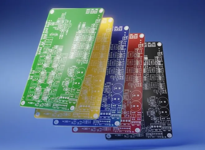
The 1.0 mm thickness and ENIG finish were deliberate choices that fit the 3D-printed enclosure and gave consistent solder joints on the XIAO's fine-pitch stamp holes and the DRV8833. Separate power pours and a solid signal ground plane reduced the motor-noise problems that had appeared in earlier wired versions. Short, controlled I2C routes kept the ToF sensor and OLED stable even when the motors were running.
Because the boards arrived quickly and correctly the first time, Tech Talkies could focus on the mechanical beta and the firmware instead of chasing manufacturing defects. The compact, reliable PCB became the stable platform that lets the robot sense edges, avoid obstacles, show expressions, and accept phone commands today—while leaving headroom for the planned servo drivetrain tomorrow.
In short, the AIVON board did not just replace wires. It turned an ambitious collection of modules into a coherent, repeatable prototype that can actually leave the workbench and live on a desk.
Inside the 6×4 cm Board: Specs That Made Everything Fit
The custom carrier board had to be small, stiff enough for the 3D-printed mounts, and quiet enough that motor switching noise would not corrupt the ToF readings or the OLED I2C bus.
|
Parameter |
Specification |
|---|---|
|
Layers |
2-layer |
|
Material |
FR-4, Tg 130–140 °C |
|
Board Thickness |
1.0 mm |
|
Copper Weight |
1 oz |
|
Surface Finish |
ENIG |
|
Via Type |
Through-hole, 0.3 mm drill |
|
Min Trace/Space |
0.15 mm / 0.15 mm |
|
Special Requirements |
Solid ground under MCU & driver, motor power pours separate from signal ground, short I2C runs to ToF and OLED, antenna keep-out for ESP32-S3 Wi-Fi |
The thin 1.0 mm board slides easily into the 3D-printed structure. ENIG gives reliable soldering on the fine pads of the XIAO and the motor-driver package. A continuous ground plane under the sensitive sections and careful separation of motor current paths keep noise manageable on a two-layer board.
Looking Ahead: A Solid Electrical Base for the Next Mechanical Leap
Desk Buddy V2 is honest about its current limitations, and that honesty is part of its charm. The electrical system works. The sensing works. The personality is already there. The next leap is mechanical—better torque, better speed control, maybe continuous-rotation servos. When that happens, the same compact PCB architecture (or a lightly revised version) will still be the reliable foundation.
If you have a desk companion, a roaming sensor platform, or any small battery-powered robot in your head, the lesson is the same: get the PCB right early. Clean power distribution, noise isolation, and manufacturable layout turn a clever idea into something you can actually iterate on.
Ready to turn your own sketch into a board that fits and works? Upload the design, get the quote, and let a factory that understands prototypes help you move from idea to something that rolls across a real desk.
FAQ
Q1: Why stay with a 2-layer PCB for a robot that has motors and a ToF sensor?
A1: A well-planned 2-layer board with solid ground and separated power pours is usually enough for this size and speed. Four layers add cost and thickness that a tiny desk robot does not need. Focus the extra attention on layout discipline instead.
Q2: How do you keep motor noise from corrupting the VL53L0X readings?
A2: Keep motor current on its own pour, place decoupling capacitors right at the DRV8833, and route the I2C lines as short and far from the motor traces as possible. A small series resistor or ferrite on the I2C lines can help further.
Q3: Is 1.0 mm board thickness strong enough for a mobile robot?
A3: Yes, when the board is supported by the 3D-printed chassis. The thin profile helps with overall weight and fit. Just make sure mounting holes and standoffs take the mechanical loads, not the PCB itself.
Q4: Why choose ENIG over HASL for this project?
A4: ENIG gives flatter, more reliable pads for the fine-pitch XIAO footprint and the motor-driver package. It also survives multiple reflow or hand-solder cycles better during prototype iterations.
Q5: What is the most common power problem in small ESP32 robot PCBs?
A5: Voltage sag when the motors start. Always put bulk capacitance near the motor driver and local decoupling at the MCU. A boost converter helps maintain the 5 V or 3.3 V rail under load.
Q6: Should the next version with servos need a completely new PCB?
A6: Probably only a minor revision. The existing layout already isolates power and signal cleanly. Changing the driver footprint and current paths is far easier than starting over from a wired prototype.