










Missing SMD Component Replacement: Step-by-Step Hot-Air PCB Repair
What This Video Covers
This video demonstrates a practical, factory-proven method to replace a missing SMD component on a finished PCB. The process begins with accurate identification of the missing part—confirming value, package size, and polarity—followed by controlled flux application, precise tweezer placement, and even hot-air heating until the solder reflows and the component seats correctly. After cleaning residual flux, a visual inspection confirms joint quality.
The technique is essential for prototype debugging, field repair, and low-volume production recovery across rigid, multilayer, and HDI PCB assemblies used in automotive PCB, industrial control, and consumer electronics. Proper execution restores electrical continuity without damaging adjacent pads or traces, reducing scrap and rework cost. For teams that need professional support beyond manual repair, PCB assembly and PCB prototype services provide controlled SMT processes that minimize missing-component occurrences from the start.
Key Highlights
- Correct component verification (value, package, orientation) before placement is the single highest-leverage step to prevent polarity or footprint mismatches.
- Controlled hot-air reflow with flux produces reliable solder joints on missing SMDs while limiting thermal stress to nearby components.
- Post-reflow flux residue removal and visual joint inspection complete the repair and confirm electrical and mechanical integrity.
Step-by-Step SMD Component Replacement Process
A missing SMD can disable an entire board. The recovery sequence shown in the video follows a repeatable engineering workflow used in repair stations and prototype labs.
First, locate the empty pads and cross-check the bill of materials or silkscreen against the replacement part. Confirm package (0402, 0603, SOT-23, etc.), value or marking, and orientation marks. Incorrect selection is the most common root cause of failed rework.
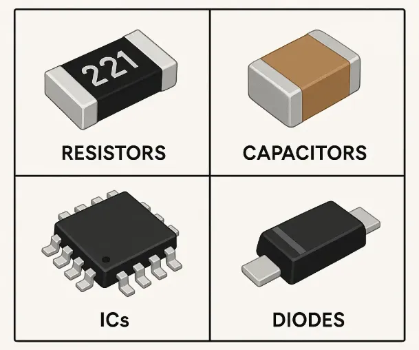
Next, apply a minimal amount of no-clean or RMA flux to the pads. Excess flux creates residue that can trap moisture or affect high-impedance circuits. Using fine-tip tweezers, place the component squarely on the pads, ensuring alignment with the land pattern.
Then heat the area with a hot-air station set to an appropriate temperature profile (typically 300–350 °C nozzle temperature for standard FR4 boards, adjusted for thermal mass). Move the nozzle in a circular motion until the solder melts and surface tension pulls the component into place. Avoid prolonged heating that can lift pads or delaminate the board.
After the joint solidifies, clean residual flux with isopropyl alcohol and inspect under magnification for fillet formation, bridging, or tombstoning. A well-executed joint restores both electrical connection and mechanical strength.
Common Failure Risks When Replacing Missing SMDs
Manual SMD replacement introduces several process risks that production SMT lines largely eliminate. Pad lifting occurs when excessive heat or mechanical force is applied to small lands, especially on thin-core or high-density boards. Tombstoning or misalignment results from uneven heating or incorrect flux volume. Bridging is common when excess solder or flux is present on fine-pitch packages.
On multilayer or HDI PCB designs, thermal gradients can stress nearby vias or microvias. In automotive or industrial applications, residual flux that is not fully removed can lead to long-term corrosion under humidity. These failure modes underscore why controlled PCB assembly processes with AOI and proper stencil design are preferred for volume production.
DFM Best Practices to Minimize Missing Component Issues
Design and process controls reduce the frequency of missing SMDs. Maintain clear silkscreen polarity marks and reference designators. Specify adequate pad sizes and solder-mask defined lands for the intended package. For prototypes, request first-article inspection and AOI coverage even on small lots.
When boards must be repaired, document the exact replacement part and process parameters. For teams scaling from prototype to production, transitioning to professional PCB prototype and turnkey PCB assembly services eliminates most manual rework variables and improves first-pass yield.
| Parameter | Recommended Practice | Risk if Ignored |
|---|---|---|
| Component verification | Match BOM value, package, polarity | Wrong part / polarity failure |
| Flux volume | Minimal, controlled application | Residue, bridging, corrosion |
| Hot-air temperature | Profile matched to board thermal mass | Pad lift, delamination |
| Post-reflow inspection | Magnified visual + continuity check | Latent open or short |
| Board type consideration | Adjust heat for FR4 vs. high-Tg or HDI | Thermal damage on sensitive stacks |
FAQ
Q1: What is the safest temperature profile for hot-air replacement of 0402 or 0603 SMDs on FR4?
A1: Start with a nozzle temperature of 300–320 °C and short dwell times, adjusting upward only as needed for larger thermal mass. Always monitor adjacent components and avoid localized overheating that can lift pads.
Q2: Can missing SMD replacement be performed reliably on HDI or fine-pitch boards?
A2: Yes, but success requires magnification, precise flux control, and lower thermal mass heating. For dense HDI designs, professional rework stations with nitrogen or controlled atmospheres are preferred over basic hot-air tools.
Q3: When should a board with a missing SMD be scrapped instead of repaired?
A3: Scrap is often more economical when multiple components are missing, pads are damaged, or the board is a high-reliability design (medical, automotive, aerospace) where rework traceability and process validation cannot be guaranteed.
Q4: Does flux residue after SMD repair affect long-term reliability?
A4: Residual flux, especially if not fully cleaned, can absorb moisture and cause leakage currents or corrosion in humid environments. No-clean fluxes still require visual verification; aqueous or solvent cleaning is recommended for critical applications.
How do you replace a missing SMD component?
Let's replace it step by step.
First, we locate the missing component and verify the correct replacement, including its value, package size, and orientation.
Next, we apply a small amount of flux to the pads and carefully place the component using tweezers.
Then, we use hot air to heat the area evenly until the solder melts and the component is securely soldered in place.
After removing any flux residue, we inspect the solder joints to make sure the repair is complete.
Sometimes, one tiny component is all it takes to bring a PCB back to life.
Like, save, and follow for more PCB soldering tips.





