










Capacitor Code Video: 104 Meaning Explained
What This Video Covers
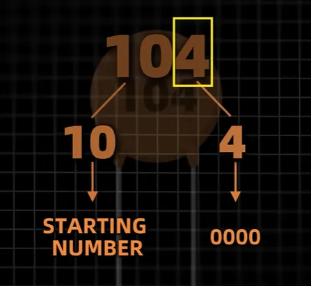
This video answers a high-frequency incoming-inspection question: what does "104" mean on a ceramic or film capacitor? It is not 104 pF. The first two digits are significant figures; the last digit is the number of zeros. So 104 is 10 followed by four zeros = 100,000 pF = 100 nF = 0.1 µF. The same rule maps 101 to 100 pF and 102 to 1 nF. A trailing letter is usually tolerance. K is commonly ±10%, J is commonly ±5%. Electrolytic cans typically skip the code and print capacitance and voltage directly (for example 100 µF, 25 V).
For OEM engineers building a PCB prototype or releasing a turnkey PCB assembly job, misreading 104 as 104 pF is a classic BOM-to-reel mismatch. Decoupling networks on consumer electronics PCB and power supply PCB designs routinely specify 100 nF ceramics; placing the wrong decade changes PDN impedance, EMI, and first-article yield. Use this decode before you request a PCB assembly quote.
Key Highlights
- 104 is 100 nF, not 104 pF. First two digits = 10; last digit = four zeros → 100,000 pF = 100 nF = 0.1 µF.
- The same EIA three-digit rule scales: 101 = 100 pF, 102 = 1 nF, 105 = 1 µF. A letter after the number is typically tolerance (J ≈ ±5%, K ≈ ±10%).
- Electrolytics usually print value and voltage in full (e.g., 100 µF 25 V). Do not apply the 104 rule to polarized cans.
How the Three-Digit Capacitor Code Works
Ceramic discs, many film capacitors, and marked MLCCs use an EIA-style three-digit code whose base unit is picofarads (pF). Digit 1 and digit 2 are the significant figures. Digit 3 is the decade multiplier, the number of zeros appended.
CpF = (first two digits) × 10(third digit)
For 104: 10 × 104 = 100,000 pF. Convert units as:
| Unit step | Value |
|---|---|
| Picofarads | 100,000 pF |
| Nanofarads | 100 nF |
| Microfarads | 0.1 µF |
That 0.1 µF (100 nF) ceramic is the default local decoupling value on most digital FR4 PCB and 4 layer PCB designs. Placing a 104 pF part instead of a 104-coded part drops decoupling by three orders of magnitude and is a frequent first-article failure.
Small values use R as a decimal point (same convention as SMD resistors): 2R2 = 2.2 pF, 0R5 = 0.5 pF. Do not treat "R" as a resistor marking when it sits on a capacitor body.
Common Codes: 101, 102, 104, and 105
The video walks the same pattern across neighboring decades. These four codes appear constantly on decoupling, coupling, and timing networks:
| Code | Calculation | pF | Common engineering label |
|---|---|---|---|
| 101 | 10 × 10¹ | 100 pF | 100 pF (RF / filter) |
| 102 | 10 × 10² | 1,000 pF | 1 nF |
| 103 | 10 × 10³ | 10,000 pF | 10 nF / 0.01 µF |
| 104 | 10 × 10⁴ | 100,000 pF | 100 nF / 0.1 µF |
| 105 | 10 × 10⁵ | 1,000,000 pF | 1 µF |
| 106 | 10 × 10⁶ | 10,000,000 pF | 10 µF (often tantalum / large MLCC) |
On op-amp and MCU boards, 103 / 104 / 105 are the usual VCC-to-GND bypass set. A 104 next to every digital IC is industry default; a 105 is often the bulk ceramic on a local rail. Mixing 104 and 105 on a reel without updating the pick-and-place program is a documented SMT defect.
Package size does not encode value. An 0402 104 and a 1206 104 are both 100 nF; voltage rating, dielectric (C0G vs X7R vs Y5V), and ESR do change with case size. Incoming inspection must read the reel label and the body code together.
Tolerance Letters After the Number (J, K, and Others)
A letter after the three-digit code is usually tolerance, not voltage.
| Letter | Typical tolerance | Where it shows up |
|---|---|---|
| F | ±1% | Precision timing, filters |
| G | ±2% | Tight analog |
| J | ±5% | Signal / general ceramic |
| K | ±10% | General-purpose bypass |
| M | ±20% | Decoupling, non-critical |
| Z | +80% / −20% | Y5V / high-K ceramics |
The video calls out K ≈ ±10% and J ≈ ±5%, the two letters technicians see most on disc ceramics. Voltage, when coded at all, is a separate EIA letter/number pair (1H = 50 V, 2A = 100 V) or is printed in volts on larger bodies. Never assume the trailing letter is voltage.
Factory risk: a 104Z ceramic can measure anywhere from ~20 nF to ~180 nF at room temperature and will drift further with bias and heat. Using Z-tolerance parts in a timing or analog filter on industrial control PCB or automotive PCB work is a DFM reject waiting to happen. Specify J or better, and lock dielectric class (C0G/NP0 vs X7R) in the AVL.
When Capacitors Do Not Use the 104 Code
Not every capacitor uses three-digit EIA coding.
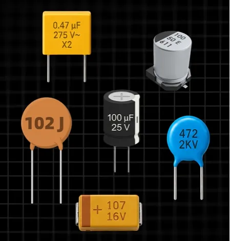
- Aluminum electrolytics print capacitance and working voltage in full: 100 µF 25 V. Polarity is marked with a stripe on the negative side. Applying the 104 rule to a can labeled "100" will invent a nonsense value.
- Many 0201 / 0402 MLCCs have no body mark. Value lives on the reel, bag, and MES scan, not on the chip. Visual ID on an unmarked 0402 is not a valid incoming method.
- Tantalums may use 107 = 100 µF plus a voltage letter (A = 10 V) and a polarity bar.
- Film boxes may print 0.1 µF 100 V or use 104J plus a voltage code.
If the body shows µF and V together, trust the print. If it shows three digits only, apply the pF multiplier rule. If it shows nothing, stop and read the reel.
Factory Incoming Inspection: Why Wrong Cap Values Fail SMT
CAM and SMT teams do not "guess" 104. The BOM line, manufacturer PN, and reel barcode must agree. Typical failure chain:
- Engineer writes "100 nF" in the schematic.
- Buyer substitutes a line item marked only "104" without converting units.
- Or a purchaser treats 104 as 104 pF and loads a 100 pF reel onto a 100 nF reference.
- First article fails PDN ripple, USB eye, or reset timing. Debug time exceeds the cost of the entire prototype lot.
Practical DFM rules used on SMT assembly lines:
- Convert every three-digit code to nF/µF on the AVL and on the traveler, not only in the CAD library.
- Do not allow unmarked 0402 ceramics as "visual verify" parts. Require reel-level traceability.
- Derate electrolytic voltage to ≤80% of rated V and keep ceramics off board flex zones to limit MLCC crack-outs.
- For HDI and fine-pitch work, pair capacitor ID with stencil aperture review via an SMT stencil check so 0402/0201 104 parts actually wet.
When you release a board for PCB mass production, lock dielectric, tolerance letter, voltage, and case size, not just "104."
FAQ
Q1: Does a capacitor marked 104 equal 104 pF?
A1: No. 104 means 10 plus four zeros = 100,000 pF = 100 nF = 0.1 µF. Treating 104 as 104 pF is a three-decade error and will fail decoupling.
Q2: What does 105 mean on a capacitor?
A2: 105 = 10 × 10⁵ = 1,000,000 pF = 1 µF. It is the next decade above 104 and is a common bulk ceramic on local rails.
Q3: Is the letter after 104 a voltage rating?
A3: Usually no. J and K are tolerance letters (±5% and ±10%). Voltage is a separate code or is printed in volts. Confirm from the datasheet before assuming voltage.
Q4: Why do electrolytic capacitors skip the 104 code?
A4: Body area is large enough to print 100 µF 25 V plus polarity. The three-digit pF code is a space-saving scheme for ceramics and small film parts, not for cans.
Q5: Can SMT incoming inspection rely on reading "104" on an 0402 MLCC?
A5: Often no. Many 0402/0201 ceramics are unmarked. Value must come from the reel label and manufacturer PN. Visual body codes are reliable mainly on discs, larger MLCCs, and film parts.
104 doesn't mean 104.
So, what does this number on a capacitor actually mean?
It's a common three-digit capacitance code.
The first two digits give you the starting number.
The last digit tells you how many zeros to add.
So 104 means 10 followed by four zeros: 100,000 pF, or 100 nF.
And the pattern continues.
101 is 100 pF.
102 is 1 nF.
You may also see a letter after the number.
That can indicate tolerance.
K commonly means ±10%, while J commonly means ±5%.
But remember, not every capacitor uses this marking system.
Some, like electrolytic capacitors, directly show the capacitance and voltage, such as 100 µF, 25 V.
Now your turn. What does 105 mean?





