










PCB Countersink vs Counterbore Holes: Critical DFM Considerations for Reliable Fabrication
What This Video Covers
Choosing the wrong hole feature can compromise mechanical integrity, screw seating, and overall product reliability. This video clearly explains the differences between countersink and counterbore in PCB design and when to use each.
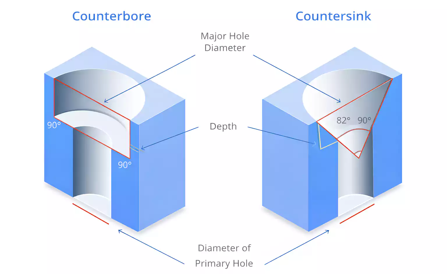
A countersink creates a conical recess for flat-head screws to sit flush with the board surface, commonly used in compact consumer electronics. A counterbore produces a flat-bottomed cylindrical recess for socket or hex-head screws, allowing the fastener head to be fully recessed while maintaining sufficient material thickness underneath.
The video highlights three essential checkpoints: matching screw head geometry, ensuring adequate remaining material thickness, and accounting for manufacturing tolerances and plating variations. Incorrect implementation can lead to poor seating, weakened structures, or assembly failures.
These features are vital for mechanical assembly in rigid PCB, aerospace PCB, medical devices PCB, and automotive electronics. Proper specification early in the design phase supports better PCB fabrication outcomes and long-term product durability.
Key Highlights
- Countersink: Creates a conical seat for flat-head screws to mount flush, ideal for space-constrained designs like consumer electronics.
- Counterbore: Provides a flat-bottom recess for socket-head screws, offering deeper concealment and better load distribution in precision assemblies.
- Design Criticals: Always verify screw geometry, maintain minimum material thickness, and consider tolerances to prevent structural weakness.
Understanding Countersink and Counterbore Features in PCB Design
Countersink holes feature a conical taper that matches the angled underside of flat-head or countersunk screws, enabling the fastener head to sit flush with or slightly below the PCB surface. This geometry is achieved through controlled drilling and routing processes that require precise angle control, typically 82°, 90°, or 100° depending on screw standards. In high-volume manufacturing, consistent conical depth is critical to prevent surface irregularities that affect automated assembly or conformal coating application.
Counterbore holes, by contrast, utilize a larger-diameter cylindrical cut with a flat bottom, creating a stepped recess that fully contains the head of socket cap or button-head screws. This design preserves more underlying laminate material, which is essential for maintaining structural integrity under vibration or thermal cycling. Production processes for counterbores often involve sequential drilling with depth stops or CNC milling, followed by deburring to ensure clean edges compatible with plating.
Both features demand careful consideration of board stack-up and copper distribution. Excessive removal of material can lead to localized stress concentrations, particularly in multilayer boards where inner-layer vias or traces may be compromised. Fabricators recommend early DFM review to validate hole specifications against available tooling and process capabilities.
Key Differences in Geometry and Mechanical Performance
The primary geometric distinction lies in the recess profile: conical for countersinks versus cylindrical flat-bottom for counterbores. This directly influences load distribution—countersinks provide excellent flush alignment but concentrate stress at the taper edges, while counterbores offer superior bearing surface area and better resistance to pull-through forces.
In terms of mechanical performance, counterbore holes generally allow greater torque application and are preferred in applications requiring repeated assembly or high clamping forces. Countersink designs excel in low-profile scenarios where protruding heads would interfere with enclosures or mating components. Manufacturing data shows that improper depth control in either feature can result in insufficient thread engagement or head protrusion, leading to field failures.
Plating considerations further differentiate the two. Both typically receive electroless copper followed by electrolytic deposition, but counterbores often require more attention to sidewall coverage due to their greater depth. Variations in plating thickness can affect final hole dimensions, making tolerance stack-up analysis a mandatory DFM step.
Table 1: Countersink vs Counterbore Comparison for PCB Applications
| Feature | Countersink | Counterbore |
|---|---|---|
| Recess Geometry | Conical (angled) | Cylindrical with flat bottom |
| Typical Screw Type | Flat-head, countersunk | Socket cap, hex, button head |
| Primary Benefit | Flush surface mounting | Deeper recess, higher load capacity |
| Material Removal | Moderate, tapered | Higher volume, stepped |
| Common Applications | Consumer electronics, slim enclosures | Aerospace, automotive, medical |
| Critical DFM Concern | Taper angle and depth consistency | Remaining material thickness |
Common Manufacturing Challenges and Failure Modes
During PCB fabrication, maintaining precise depth control presents a significant challenge, especially on boards with varying copper weights or asymmetric stack-ups. Over-drilling countersinks can breach critical inner layers or reduce dielectric thickness below safe limits, while insufficient counterbore depth leaves screw heads proud, causing assembly interference.
Plating inconsistencies, such as dog-boning or thin sidewall coverage in deeper features, can lead to poor solderability or long-term corrosion issues. In high-reliability sectors, these defects often trigger costly rework or scrap. Vibration testing frequently reveals failures originating from stress risers at poorly executed recess edges.
Tolerances compound these risks. Standard fabrication tolerances of ±0.1 mm or greater on hole features can shift screw seating from acceptable to problematic, particularly for M2.5 and smaller fasteners common in dense designs.
DFM Best Practices for Specifying Countersink and Counterbore Holes
Designers should provide detailed drawings specifying hole diameters, depths, angles, and tolerances, including callouts for remaining material thickness (typically at least 0.3–0.5 mm depending on board thickness). Collaboration with the fabricator during the DFM review phase allows optimization of tool selection and process sequencing.
It is recommended to avoid placing high-density traces or vias directly beneath these features and to incorporate generous keep-out zones. For plated holes, specify minimum copper thickness and verify via IPC standards. Prototype runs with X-ray or cross-section analysis help validate actual versus specified dimensions before volume production.
Material Thickness and Tolerance Requirements in Production
Maintaining adequate remaining laminate thickness beneath counterbore holes is essential for mechanical strength and thermal dissipation. Industry practice suggests a minimum of 0.5 mm for standard FR-4 boards in moderate stress applications, increasing for high-vibration environments.
Countersink depth must be tightly controlled to prevent the conical section from intersecting critical copper layers. Advanced fabricators use laser depth control or precision CNC equipment to achieve repeatability within ±0.05 mm. Accounting for material compression during lamination and plating buildup is crucial for final tolerance compliance.
Table 2: Recommended Minimum Remaining Material Thickness Guidelines
| Board Thickness | Countersink Min. Remaining | Counterbore Min. Remaining | Application Notes |
|---|---|---|---|
| 0.8 mm | 0.3 mm | 0.4 mm | Consumer, low-stress |
| 1.6 mm | 0.5 mm | 0.6 mm | Standard industrial |
| 2.4 mm+ | 0.8 mm | 1.0 mm | Aerospace, automotive, medical |
FAQ
Q1: What is the main difference between countersink and counterbore in PCBs?
A1: Countersink creates a conical recess for flat-head screws to sit flush. Counterbore creates a flat-bottom cylindrical recess for socket or hex-head screws to be fully hidden.
Q2: When should I choose counterbore over countersink?
A2: Choose counterbore when using socket-head screws that need complete recessing, higher load bearing, or when preserving more material thickness is critical for structural strength.
Q3: What are the most common mistakes with PCB countersink/counterbore?
A3: Mismatching screw head geometry, insufficient remaining material thickness, or ignoring manufacturing tolerances and plating effects, which can lead to weak assemblies or installation failures.
Q4: How do plating requirements differ for countersink and counterbore holes?
A4: Counterbore holes often require more robust sidewall plating due to greater depth and aspect ratio, while countersinks demand precise control at the tapered transition to avoid thinning. Both benefit from specifying minimum copper thickness per IPC-6012 standards to ensure reliable conductivity and mechanical integrity.
Q5: What tolerances should be applied to PCB countersink and counterbore features?
A5: Typical depth tolerances range from ±0.05 mm to ±0.1 mm depending on board complexity and fabricator capabilities. Always include these in fabrication notes and verify through first-article inspection, especially for Class 3 products in aerospace or medical applications.
Are you choosing the right hole type—or weakening your assembly without knowing it?
A countersink creates a conical seat for flat-head screws to sit flush.
Match the angle to ensure proper seating.
And it's used for flush screw heads in products like phones and laptops.
A counterbore forms a flat-bottom recess for socket or hex-head screws.
It must fully seat the screw head while preserving enough material underneath.
It's used to fully hide screw heads in precision or aerospace assemblies.
Three key checkpoints:
First, verify screw head geometry before defining the hole.
Second, ensure minimum material thickness under the feature.
Third, account for manufacturing tolerance and plating variation.
Common in design—but only safe when geometry, depth, and strength are properly controlled.





