










SMT vs THT PCB Assembly: Why Both Technologies Remain Essential
What This Video Covers
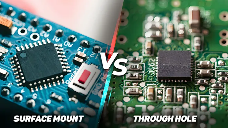
This video clarifies the fundamental differences between SMT (Surface Mount Technology) and THT (Through-Hole Technology) and explains why both mounting methods continue to play important roles in today's PCB designs.
SMT solders components directly onto the board surface, enabling smaller footprints, higher component density, and faster automated PCB assembly. It is the preferred choice for resistors, capacitors, processors, and most high-volume electronics. However, its smaller solder joints are more vulnerable to vibration, thermal cycling, and mechanical stress.
THT passes component leads through drilled and plated holes before soldering, delivering superior mechanical strength and reliability. This makes it ideal for connectors, transformers, large capacitors, and parts subject to physical stress.
Most practical designs use a hybrid approach: SMT for density and manufacturing efficiency combined with THT for structural integrity. The video helps engineers make informed decisions during PCB prototype and PCB mass production to balance performance, cost, and long-term reliability in demanding applications such as automotive PCB, medical devices PCB, and aerospace PCB.
Key Highlights
- SMT delivers smaller size, higher routing density, and faster automated assembly but has weaker mechanical joints under stress.
- THT provides strong plated-hole mechanical support, making it essential for connectors, transformers, and high-stress components.
- Most reliable PCB designs combine both technologies: SMT for density and THT for strength.
Fundamental Differences Between SMT and THT Mounting
Surface Mount Technology mounts components directly on copper pads using solder paste and reflow soldering, eliminating the need for drilled holes in most cases. This enables finer pitch components, multilayer routing optimization, and significant reductions in board size. In high-volume production, SMT lines achieve higher throughput with pick-and-place machines operating at thousands of components per hour.
Through-Hole Technology requires precise drilling and plating of holes, followed by wave or selective soldering. The resulting mechanical interlock between component leads and the PCB provides robust anchoring that resists shear forces far better than surface solder joints. However, THT consumes more board real estate and increases drilling costs.
In practice, the choice between SMT and THT affects not only layout but also thermal management, signal integrity, and long-term field performance. Production teams must coordinate DFM reviews early to avoid costly revisions between prototype and mass production stages.
Key Advantages and Limitations in Real Production Environments
SMT excels in miniaturization and cost efficiency for consumer and portable electronics, where board space and assembly speed drive profitability. Yet, in environments with extreme vibration or thermal shock — such as under-hood automotive modules or industrial control systems — SMT joints can develop micro-cracks leading to intermittent failures or open circuits over time.
THT components offer excellent heat dissipation for high-power parts and superior resistance to mechanical pull-out forces, making them standard for edge connectors and large inductors. The trade-off appears in lower assembly automation rates and higher material costs due to hole drilling and larger component packages.
Manufacturing data consistently shows hybrid boards achieve the best balance. Selective soldering processes allow precise application of THT while maintaining high-speed SMT lines, minimizing defects and optimizing overall yield.
Hybrid SMT-THT Designs: Best Practices for Reliability
Successful hybrid designs strategically place THT components in high-stress zones while maximizing SMT for the majority of the circuitry. DFM principles recommend early collaboration between designers and manufacturers to define keep-out zones around THT holes, optimize solder mask expansion, and ensure adequate clearance for wave soldering pallets.
Thermal profiling becomes critical in mixed assemblies to prevent tombstoning of SMT parts or insufficient fillet formation on THT joints. Reliable production often incorporates selective soldering robots for THT sections, allowing reflow optimization for SMT without compromising through-hole integrity.
In automotive and medical applications, hybrid approaches frequently pass stringent vibration and thermal cycling tests where pure SMT designs fail qualification. Proper via stitching around THT pads further enhances mechanical and thermal performance.
Component Selection Guidelines for Demanding Applications
| Component Type | Recommended Technology | Primary Reasons | Typical Applications |
|---|---|---|---|
| Resistors & Capacitors (small) | SMT | High density, low cost, fast assembly | Consumer electronics, dense PCBs |
| Connectors & Switches | THT | Mechanical strength, vibration resistance | Automotive, industrial controls |
| Transformers & Inductors | THT or Hybrid | High power handling, heat dissipation | Power supplies, medical equipment |
| Large Electrolytic Caps | THT | Superior hold strength, ripple current | Power circuits, aerospace systems |
| Processors & ICs | SMT | Fine pitch, high I/O count | Computing, communication modules |
This selection guide helps procurement and engineering teams specify the optimal mix during the DFM phase, reducing assembly defects and field failure rates.
FAQ
Q1: When should designers choose THT over SMT components?
A1: Choose THT for components that experience mechanical stress, vibration, or high current, such as connectors, transformers, and large capacitors where superior hold strength is required.
Q2: What are the main advantages of SMT over THT in PCB assembly?
A2: SMT offers smaller component size, higher density layouts, lower production costs, and faster automated assembly compared to THT.
Q3: Can a single PCB design effectively use both SMT and THT?
A3: Yes — hybrid designs are standard practice, using SMT for most components and THT where mechanical reliability or high power handling is critical.
Q4: How do thermal and vibration stresses affect SMT vs THT joints in field operation?
A4: SMT joints are more susceptible to fatigue cracking under repeated thermal cycling and vibration due to their smaller contact area. THT joints provide better strain relief through the board thickness. In automotive and aerospace applications, hybrid designs are often mandatory to meet reliability specifications.
Q5: What DFM considerations are essential when planning hybrid SMT-THT boards?
A5: Key considerations include hole positioning to avoid interfering with fine-pitch SMT components, adequate clearances for selective soldering nozzles, and thermal relief designs around THT pads. Early manufacturer involvement prevents costly layout revisions and improves first-pass yield.
Tiny black chips.
Long metal pins.
Why do PCB components use different mounting styles?
On a PCB, most components use SMT or THT.
SMT, Surface Mount Technology, solders parts directly onto the PCB surface.
Resistors, capacitors, sensors, and processors are usually SMT.
Why SMT?
Smaller size.
Higher routing density.
Faster automated assembly.
But there's a tradeoff.
Small solder joints can crack under vibration, heat cycling, or repeated stress.
That's why THT still exists.
THT, Through-Hole Technology, passes leads through drilled holes before soldering.
The plated hole gives stronger mechanical support.
So connectors, transformers, buttons, and large capacitors still use THT.
Most real PCB designs combine both:
SMT for density and speed,
THT for strength and reliability.





