










Through-Hole Components Replacement: Professional Techniques for Reliable PCB Repairs
What This Video Covers
This video provides a detailed, step-by-step guide to safely removing through-hole components on a PCB, minimizing risk of damage to pads, traces, or the board itself. The process is broken into three critical stages: safe removal, thorough hole clearing, and reliable reinstallation.
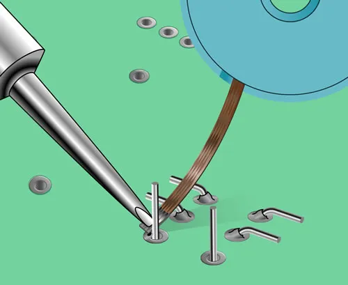
Step one focuses on using a properly heated soldering iron, adding fresh solder to each pin, and gently removing the old component. Step two emphasizes reheating and using a solder sucker to completely clear all holes for a clean fit. Step three covers precise placement of the new component and ensuring each joint is fully wetted with good fillet formation for mechanical and electrical integrity.
These techniques are fundamental for successful PCB prototype debugging, field repairs, and PCB assembly rework. Proper through-hole soldering directly impacts reliability in demanding applications such as medical devices, automotive electronics, industrial control systems, and power electronics. Mastering this process helps engineers and technicians achieve first-time-right results and reduce costly mistakes.
Key Highlights
- Safe Component Removal: Heat each pin with a soldering iron, add fresh solder, and lift gently to avoid damaging pads or traces.
- Complete Hole Clearing: Use a solder sucker while reheating to ensure every through-hole is fully open and clean for the new part.
- Proper Installation: Install the new component flat and create strong, fully wetted solder joints on every pin for maximum reliability.
Step-by-Step Process for Safe Component Removal
Successful through-hole components replacement begins with controlled heating to prevent thermal shock or mechanical damage. In production environments, technicians apply fresh solder to each pin before removal. This refreshes the joint and lowers the melting point, allowing the component to release with minimal force. Excessive heat or prolonged contact can delaminate pads or lift traces, especially on multilayer boards common in automotive and medical applications.
Real manufacturing scenarios often involve components with multiple pins or high thermal mass, such as connectors and transformers. Sequential heating of pins is critical to avoid uneven stress. After loosening, the component should lift cleanly without prying. Failure to follow this sequence frequently results in lifted pads, a common defect that requires extensive repair or board scrapping.
Proper temperature control, typically 320–380°C depending on solder alloy and board thickness, combined with appropriate tip selection, ensures repeatability across batches of rework. These practices align with industry standards for high-reliability electronics where joint integrity directly affects product lifespan.
Complete Hole Clearing Methods and Best Practices
Residual solder in through-holes after component removal creates significant assembly issues. The video demonstrates reheating each hole while applying a solder sucker to extract molten solder completely. Incomplete clearing leads to misaligned new components, insufficient solder fillet formation, and potential open circuits under vibration or thermal cycling.
In high-volume manufacturing and field service, technicians often encounter oxidized or contaminated holes that resist cleaning. Multiple passes with a solder sucker or the use of desoldering braid may be required. Board thickness, hole diameter, and copper weight influence the difficulty. For dense boards, vacuum desoldering tools provide superior results compared to manual suckers.
Best practice includes inspecting each hole under magnification after clearing. Blocked holes increase the risk of poor wetting and voids, which can fail reliability testing in automotive or industrial environments. Thorough cleaning also facilitates better flux activation during reinstallation, contributing to stronger mechanical bonds.
Proper Installation and Solder Joint Formation
Accurate placement and controlled soldering complete the through-hole components replacement process. The new component must seat flush against the board to maintain designed standoff and thermal performance. Solder is applied to form concave fillets that fully wet both the pad and lead, indicating proper intermetallic bonding.
Visual inspection criteria include a shiny appearance without cracks or cold solder joints. In production, excessive solder can cause bridging while insufficient solder reduces mechanical strength. Temperature profiling and dwell time are critical, particularly for components with varying pin sizes on the same board.
These joints must withstand environmental stresses including vibration, humidity, and thermal expansion. Following established procedures minimizes defects such as tombstoning or insufficient fillet, which are frequent causes of field failures in repaired assemblies.
Common Manufacturing Challenges in Through-Hole Rework
Through-hole components replacement frequently encounters challenges related to board condition and component type. Heat-sensitive components nearby may require shielding or selective heating tools. Multilayer boards with heavy copper planes dissipate heat rapidly, demanding higher power stations or preheating.
Common failure modes include pad lifting due to repeated rework cycles, trace damage from excessive force, and contamination from flux residues. In medical and automotive sectors, these defects can trigger strict quality holds or recalls. Mitigation involves documented rework procedures, operator training, and post-rework cleaning and inspection protocols.
Design for Manufacturability (DFM) Considerations for Through-Hole Components
Effective DFM for through-hole technology incorporates adequate pad sizes, annular rings, and hole diameters to support reliable rework. Designers should consider component thermal mass and recommended soldering profiles during layout. Larger pads and strategic trace routing improve heat distribution and repairability.
Specifying component orientation and test point placement can streamline both initial assembly and future maintenance. Collaboration between design and manufacturing teams early in the process reduces rework frequency and enhances overall product reliability in demanding applications.
Recommended Parameters
| Parameter | Recommended Value | Impact on Rework |
|---|---|---|
| Soldering Iron Temperature | 320–380°C | Prevents thermal damage while ensuring complete melt |
| Hole Diameter Tolerance | +0.1 mm typical | Facilitates component insertion and solder flow |
| Annular Ring Width | ≥0.2 mm | Reduces risk of pad lifting during removal |
| Solder Alloy | Sn63/Pb37 or lead-free SAC305 | Affects wetting time and joint strength |
Tools and Equipment Recommendations for Professional Results
Professional through-hole rework requires temperature-controlled soldering stations, quality solder suckers or desoldering guns, flux, and magnification tools. Selection of appropriate tip geometries for different pin sizes enhances efficiency and reduces collateral damage.
FAQ
Q1: What is the correct way to remove a through-hole component without damaging the PCB?
A1: Heat each pin individually with a soldering iron at the right temperature, add a small amount of fresh solder, and gently lift the component once the solder is molten. Avoid excessive force.
Q2: Why must you fully clear the holes after removing a through-hole part?
A2: Blocked or partially filled holes prevent the new component from seating correctly, leading to poor connections, alignment issues, or unreliable solder joints.
Q3: What makes a good solder joint when installing a new through-hole component?
A3: The solder should fully wet both the pad and the lead, forming a smooth, concave fillet. The joint must be shiny, without cold solder appearance or excessive solder.
Q4: How does board thickness affect through-hole components replacement?
A4: Thicker boards with heavy copper layers require higher heat input or preheating to achieve proper solder flow. Insufficient heat leads to incomplete wetting and weak joints, while excessive heat increases the risk of delamination. Process parameters must be adjusted according to the specific stack-up.
Q5: When should desoldering braid be used instead of a solder sucker?
A5: Desoldering braid is effective for residual solder on pads or when clearing very small holes. It provides precise control in tight spaces or on boards where vacuum tools might cause damage. Combining both tools often yields the best results in complex rework scenarios.
How to properly replace a through-hole component?
Step one, remove the part.
Use a soldering iron at the right temperature.
Heat each pin, add a bit of fresh solder,
and lift it out gently.
Step two, clear the holes.
Reheat and use a solder sucker.
Every hole must be fully open.
Step three, install the new part.
Place it flat, then solder each pin.
Make sure the solder fully wets the leads.
Removing gets it out.
Installing makes it work.
If the joints aren't right, the job isn't done.





