










Remove Plastic Connector from PCB Without Melting It: Expert Rework Techniques
What This Video Covers
This video demonstrates safe plastic connector removal during PCB rework and repair. It focuses on the critical balance of temperature and exposure time to prevent melting while achieving clean separation from pads and traces.
The content highlights engineering best practices that protect multilayer, HDI, and rigid-flex board structures, preserving signal integrity and long-term reliability. Proper connector removal is essential when modifying or repairing high-value assemblies used in aerospace, automotive electronics, medical devices, and industrial control systems.
OEM engineers and repair teams will gain actionable insights for minimizing damage during rework. For pricing on assembly or rework projects, request an instant PCB assembly quote or explore full PCB assembly services.
Key Highlights
- Strict temperature and time control prevents melting of plastic connectors while protecting pads, traces, and underlying layers on multilayer and HDI PCBs.
- Clean removal techniques minimize mechanical stress and maintain board integrity for reliable performance in aerospace, automotive, and medical electronics.
- These methods support high-yield rework and repair of industrial control and IoT assemblies without compromising signal integrity or thermal management.
Understanding Thermal Challenges in PCB Plastic Connector Removal
Plastic connectors in modern PCBs often use materials such as PA, PBT, or LCP that have relatively low glass transition temperatures. During removal, excessive heat can cause housing deformation, pin misalignment, or contamination of solder joints. In multilayer and HDI constructions, prolonged heat exposure risks via delamination, pad lifting, and inner-layer separation, particularly in boards with high copper weights or dense via arrays.
Real production environments show that even minor overheating—often by 20–30°C above optimal—can initiate micro-cracks in FR-4 laminates or weaken plated through-holes. These defects may pass initial visual inspection but lead to field failures under thermal cycling or vibration, common in automotive and aerospace applications. Effective DFM requires early consideration of connector types, housing profiles, and pin densities to facilitate future rework.
Key Process Parameters for Damage-Free Connector Extraction
Successful PCB plastic connector removal depends on precise control of hot-air temperature, airflow rate, nozzle selection, and dwell time. Typical recommended settings range from 280–320°C with low-to-medium airflow for most connectors, adjusted according to housing size and board thermal mass.
Connector Removal Parameters
| Connector Type | Recommended Temperature (°C) | Max Exposure Time (s) | Preferred Tool | Key Risk if Exceeded |
|---|---|---|---|---|
| Standard 2.54mm Pin Headers | 280–300 | 8–12 | Hot-air station with 5–7mm nozzle | Housing melt, pad lift |
| High-Density Board-to-Board | 290–310 | 6–10 | Precision hot-air with preheater | Via damage, trace delamination |
| Automotive-grade Sealed Connectors | 300–320 | 10–15 | IR-assisted rework system | Moisture-induced popcorning |
| Rigid-Flex Assemblies | 270–295 | 5–8 | Low-temperature hot-air | Flex layer separation |
Preheating the entire board to 100–120°C significantly reduces localized thermal shock and improves removal success rates.
Step-by-Step Safe Removal Methods for Multilayer and HDI Boards
Begin by documenting connector orientation and surrounding components. Apply flux to solder joints and use a preheater to stabilize board temperature. Direct controlled hot air at the connector pins while gently applying minimal mechanical assistance once solder reaches liquidus. Avoid prying before full reflow to prevent trace tearing.
Post-removal, clean residual solder with wick or vacuum desoldering tools, then inspect pads and vias under magnification for cracks or lifting. For HDI boards, X-ray or flying-probe testing may be necessary to verify inner-layer integrity. These procedures maintain the original design intent and support repeated rework cycles when required by engineering change orders.
Common Failure Modes and Prevention Strategies
The most frequent issues include partial melting of connector housings that leaves residue on pads, lifted pads due to excessive force, and hidden delamination that appears only during functional testing or environmental stress screening. Prevention centers on strict adherence to documented thermal profiles, operator training, and use of calibrated equipment.
DFM recommendations include specifying rework-friendly connector footprints with adequate clearance and thermal reliefs where possible. In high-volume production, implementing automated optical inspection (AOI) after rework helps catch subtle defects early.
Industry-Specific Considerations for High-Reliability Applications
Aerospace and medical device assemblies often require full process validation, including thermal profiling reports and traceability of rework tools. Automotive applications under IATF 16949 emphasize zero-defect goals, making controlled PCB plastic connector removal critical for warranty performance. Industrial systems benefit from these techniques to extend product life in harsh environments.
FAQ
Q1: How do you prevent melting plastic connectors during PCB rework?
A1: Use high-grade flux, a focused hot air nozzle with steady circular motion, and precise temperature control. Avoid concentrating heat in one spot and never exceed necessary dwell time.
Q2: What tools are essential for safe plastic connector removal?
A2: A professional hot air rework station, quality flux, fine nozzle, and lint-free wipes with isopropyl alcohol for cleanup are critical for protecting both the connector and the PCB.
Q3: Why is flux cleanup important after connector removal?
A3: Residual flux can cause long-term corrosion, electrical leakage, or contamination. Proper cleaning with IPA ensures a pristine surface and maximum reliability of the repaired board.
Q4: What are the risks of improper plastic connector removal in automotive PCBs?
A4: Improper removal can lead to warped housings causing intermittent connections, lifted pads resulting in open circuits, or flux residue inducing dendritic growth. These issues contribute to warranty failures and safety concerns; following documented DFM-guided rework procedures mitigates such risks effectively.
Q5: How does connector design influence rework success rates?
A5: Connectors with higher temperature-rated plastics, staggered pin layouts for better heat access, and built-in thermal barriers allow safer removal. Early collaboration between design and manufacturing teams to incorporate these features improves first-pass yields during both initial assembly and field repairs.
Removing a plastic-housed connector without warping the casing is a true test of thermal control. To prevent melting, precision is paramount. We start by applying high-grade flux to the leads, ensuring efficient heat transfer to the solder joints while protecting the delicate plastic body.
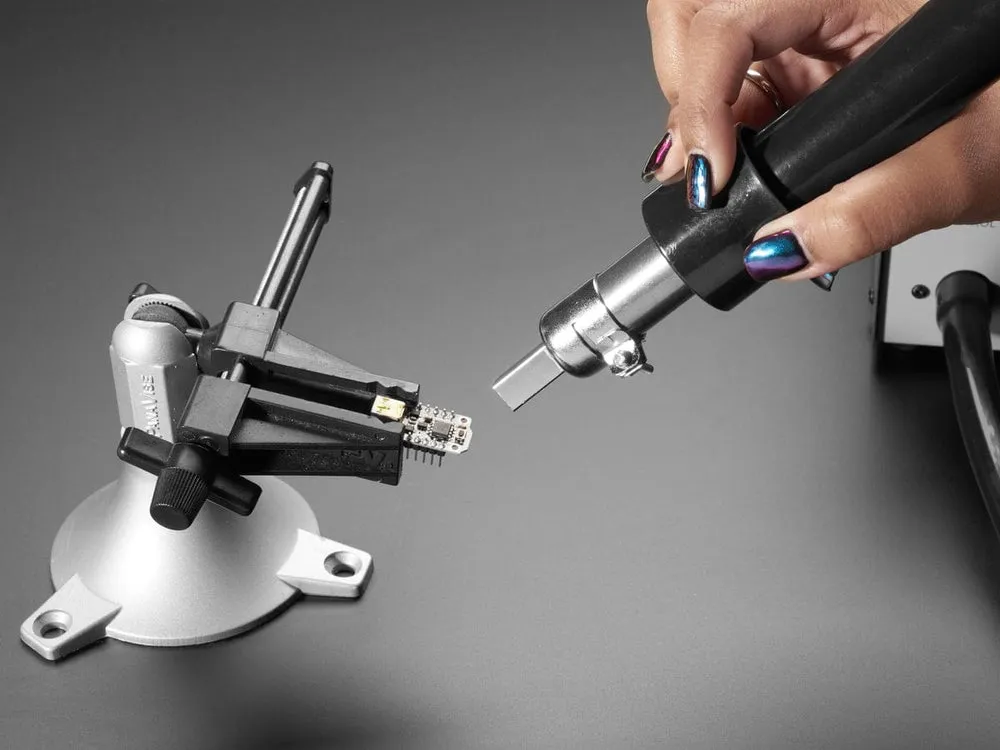
Using a hot air rework station with a focused nozzle, we maintain a steady, circular motion to avoid localized overheating. Once the solder reaches its liquidus state, the connector is lifted gently—no force required. Finally, we use a lint-free wipe and IPA to clear away all flux residue. No scorched plastic, no lifted pads—just a clean, professional result.





