










Hot Air Gun Settings for Safe PCB Rework
What This Video Covers
This video provides practical guidance on using a hot air gun correctly for PCB rework, addressing the most frequent causes of failed component removal and board damage. Incorrect settings — excessive airflow, wrong temperature, or poor nozzle technique — can blow small parts off the board, lift pads, or overheat nearby components.
Recommended settings include 330–350°C for leaded solder and 350–370°C for lead-free solder. Airflow levels of 2–3 suit small resistors and capacitors, while 3–4 work better for larger ICs. The video emphasizes even nozzle movement, checking component datasheets, and using high-temperature tape to protect sensitive areas.
Mastering these techniques significantly improves success rates during PCB prototype troubleshooting and PCB assembly repairs. Proper hot air rework helps preserve signal integrity and board reliability across demanding applications such as medical devices PCB, automotive PCB, and industrial control PCB.
Key Highlights
- Use 330–350°C for leaded and 350–370°C for lead-free solder, adjusting airflow based on component size to ensure full reflow without damage.
- Maintain proper nozzle distance and movement while protecting nearby parts with high-temperature tape during rework.
- Avoid excessive heat or airflow that can dislodge small components or lift pads on the PCB.
Recommended Temperature Ranges for Leaded and Lead-Free Solder
Leaded solder alloys typically reflow reliably between 330 °C and 350 °C. Lead-free formulations require higher peak temperatures in the 350–370 °C range to achieve full melting without prolonged exposure. These windows balance reflow speed against the thermal limits of most FR-4 laminates and component packages.
Exceeding 370 °C on standard boards accelerates resin degradation and can cause copper pad adhesion failure, especially on thin traces or fine-pitch footprints. Conversely, temperatures below the recommended floor leave solder paste or joints only partially molten, forcing operators to increase dwell time and raise the risk of heat transfer into neighboring parts.
Component datasheets should always be checked for maximum reflow temperature ratings. Many ceramic capacitors and small ICs specify lower limits than the board laminate can tolerate. In practice, starting at the lower end of the appropriate range and increasing only as needed produces more consistent results than beginning at the upper limit.
When working on boards that mix leaded and lead-free components, the higher lead-free window is normally selected, with additional shielding applied to any temperature-sensitive parts. Controlled temperature selection directly supports DFM goals by preserving pad integrity and reducing the need for subsequent repair cycles.
Airflow Selection by Component Size and Board Density
Airflow level determines both heat transfer rate and mechanical force applied to the board surface. Levels 2–3 are suitable for small chip resistors, capacitors, and discrete semiconductors because the lower air volume reduces the chance of physically displacing the part once the solder melts. Levels 3–4 provide the additional thermal mass needed for larger QFP, QFN, or BGA packages without requiring excessive temperature.
High board density further constrains airflow choice. Closely spaced components create turbulent flow paths that can redirect hot air onto adjacent devices. In these cases the lower airflow setting combined with a smaller nozzle often proves more controllable than increasing volume.
Operators who default to maximum airflow frequently observe small 0402 or 0201 parts blowing free of their pads the moment the solder reaches liquidus. The resulting open circuits or tombstoned components require additional rework and can damage surrounding copper. Matching airflow to component thermal mass and board population density therefore forms a core DFM control point for reliable SMT rework.
| Component Type | Recommended Airflow Level | Typical Temperature Range | Primary Risk if Exceeded |
|---|---|---|---|
| 0201 / 0402 resistors & caps | 2–3 | 330–350 °C (leaded) | Blow-off or tombstoning |
| SOIC / SOT packages | 2–3 | 340–360 °C | Pad lift on fine leads |
| QFP / QFN / larger ICs | 3–4 | 350–370 °C (lead-free) | Adjacent component overheating |
| Small BGA or CSP | 3–4 | 355–370 °C | Uneven reflow or board warpage |
Nozzle Distance, Movement, and Heat Distribution Techniques
Maintaining a consistent nozzle-to-board distance of approximately 5–10 mm, combined with continuous circular or figure-eight motion, distributes heat evenly across the target joint. Stationary positioning creates localized hot spots that can delaminate the outer copper layers or crack ceramic packages.
Nozzle diameter should match the component footprint as closely as practical. Oversized nozzles waste heat energy and increase exposure to neighboring areas; undersized nozzles prolong the process and raise the risk of incomplete reflow under large thermal-mass packages.
In production and prototype environments, operators who combine proper distance with steady motion achieve higher first-pass success rates and fewer instances of lifted lands. These technique details translate directly into reduced scrap and improved board reliability after rework.
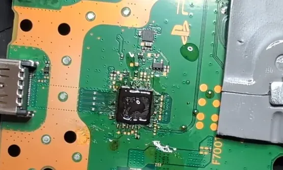
Component Protection Methods and Adjacent Area Shielding
High-temperature polyimide tape or aluminum foil shields provide an effective barrier against stray airflow and radiant heat. Sensitive components such as electrolytic capacitors, connectors, and plastic-bodied devices are routinely masked before heat is applied.
Tape application must leave the target component fully exposed while overlapping neighboring pads by at least 1–2 mm. Incomplete coverage allows hot air to undercut the shield and still transfer damaging heat. After rework, residual adhesive is cleaned with isopropyl alcohol to avoid contamination of subsequent assembly steps.
When multiple nearby parts require protection, sequential masking combined with the lowest effective airflow setting minimizes cumulative thermal stress. These protective practices form a practical extension of DFM principles into the rework station itself.
Common Failure Modes Caused by Incorrect Hot Air Parameters
Excessive airflow is the leading cause of component displacement. Once solder reaches liquidus, even moderate air pressure can move lightweight passives off their pads. Pad lift occurs when temperature exceeds the copper-to-laminate adhesion limit or when heat is applied too long after the joint has already reflowed.
Thermal gradient damage appears as micro-cracks in ceramic capacitors or delamination of multilayer boards, especially those with high copper density. In high-reliability sectors such as medical device PCB and automotive PCB assemblies, these latent defects can escape visual inspection yet fail under subsequent thermal cycling or vibration.
Recognizing the link between parameter selection and specific failure signatures allows technicians to adjust settings before irreversible damage occurs. Systematic avoidance of the common error modes described above improves both immediate rework yield and long-term field reliability.
DFM Considerations for High-Reliability PCB Rework Applications
Design for manufacturability extends beyond initial fabrication into repair processes. Boards intended for medical, automotive, or industrial control applications often incorporate tighter thermal constraints, higher copper weights, or specialized surface finishes that alter heat response.
Selecting the lowest viable temperature and airflow combination, combined with thorough adjacent-component shielding, preserves signal integrity and mechanical strength after rework. Documentation of the exact settings used for each component type further supports process repeatability and traceability requirements common in regulated industries.
When these controlled practices are applied consistently, hot air rework becomes a reliable extension of the original manufacturing process rather than a source of secondary defects.
FAQ
Q1: What are the correct temperature settings for hot air rework on PCBs?
A1: Use 330–350°C for leaded solder and 350–370°C for lead-free solder, always verifying against component datasheets when possible.
Q2: How do you choose airflow level when using a hot air gun for PCB rework?
A2: Set airflow to level 2–3 for small components like resistors and capacitors, and 3–4 for larger ICs to achieve even heating without blowing parts away.
Q3: How can you protect nearby components during hot air rework?
A3: Apply high-temperature tape to shield sensitive parts and maintain controlled nozzle movement to prevent overheating adjacent areas.
Q4: Why do small SMD components frequently blow off the board during rework?
A4: Excessive airflow combined with fully molten solder creates enough force to displace lightweight 0201 or 0402 parts. Reducing airflow to level 2–3 and using a correctly sized nozzle prevents this common failure.
Q5: Can incorrect hot air settings damage multilayer PCB integrity?
A5: Yes. Prolonged or excessively high temperature can weaken copper-to-laminate adhesion, cause internal delamination, or create micro-cracks in ceramic components. Staying within the documented temperature windows and limiting dwell time reduces these risks.
How do you use a hot air gun correctly?
Wrong settings can make PCB rework much harder.
Too much airflow can blow small components off the board.
Too much heat can damage pads and sensitive devices.
Too little heat may prevent the solder from fully melting.
And a poorly aimed nozzle can overheat nearby components.
So here are some common settings:
For leaded solder, 330–350°C is commonly used.
For lead-free solder, 350–370°C is more typical.
Small resistors and capacitors usually work well with airflow level 2 to 3.
Larger ICs often require airflow level 3 to 4.
Some components also have specific temperature requirements, so always check the datasheet when possible.
And when working near sensitive parts, use high-temperature tape for protection.
Good settings lead to better rework results.
Like and save for future repairs.





