










Soldering Iron vs Hot Air: Choosing the Right Tool for PCB Soldering and Rework
What This Video Covers
This video provides a clear comparison between soldering irons and hot air rework stations, helping engineers and technicians choose the right tool for different PCB soldering and rework scenarios. While both tools melt solder, their heat delivery methods are fundamentally different and impact results significantly.
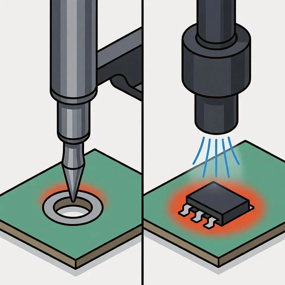
A soldering iron delivers focused, point-specific heat through direct tip contact with the pad. This makes it ideal for through-hole components, precise repairs, and fine-pitch work. In contrast, hot air stations distribute heat broadly across multiple joints simultaneously, making them the preferred choice for SMD components, QFN/BGA packages, and component removal during rework.
The video covers key control factors such as tip size, airflow settings, and the critical role of flux in ensuring proper solder flow. Understanding these differences helps prevent common issues like cold joints, lifted pads, or component damage. These techniques are essential for PCB prototype development, SMT assembly, and repairs in demanding applications like medical devices, automotive electronics, and industrial control systems.
Key Highlights
- Soldering Iron Advantages: Provides precise, localized heat — perfect for through-hole parts, fine repairs, and detailed soldering work.
- Hot Air Station Strengths: Delivers even heat across multiple joints — ideal for SMD components, rework, and safe component removal.
- Tool Selection & Flux: Match the tool to the task and always use flux for better flow, thermal transfer, and professional results.
Understanding Heat Delivery Differences Between Soldering Irons and Hot Air Stations
Soldering irons transfer heat through direct conduction via the tip, creating a rapid temperature rise at the exact point of contact. This method offers excellent control for single-joint work but can lead to uneven heating on larger thermal mass areas or multi-pin components. In production environments, improper tip selection or dwell time often results in insufficient wetting or overheating of adjacent traces.
Hot air stations, conversely, utilize convective heat transfer. Controlled airflow and temperature settings allow uniform heating across an area, which is particularly valuable when thermal reliefs or ground planes are present. However, excessive airflow can displace small components or cause solder splatter if not properly managed.
In real manufacturing scenarios, the choice directly affects first-pass yield. Conduction-based tools excel in low-volume prototyping where precision trumps speed, while convection tools support higher throughput in rework stations for surface-mount technology. Proper nozzle selection and preheat profiles are critical DFM considerations to minimize board warpage and intermetallic compound growth.
Component-Specific Applications and Tool Selection Guidelines
Through-hole components benefit most from soldering irons due to the need for targeted heat on leads and pads. Fine-pitch work and jumper wires also favor irons because surrounding components remain largely unaffected.
SMD resistors, capacitors, and ICs with multiple pins perform better with hot air. The simultaneous heating reduces the risk of tombstoning or skewing during reflow. For QFN and BGA packages, hot air combined with proper stencil-applied solder paste and flux is often the only practical method for reliable rework without specialized equipment.
Production data consistently shows that mismatched tooling increases defect rates. For example, attempting hot air on fine-pitch through-hole connectors can cause bridging, while using an iron on dense SMD arrays frequently leads to insufficient heat on center pins.
Tool Selection Guide
| Component Type | Recommended Primary Tool | Secondary Tool | Use Case | Key Parameter Considerations |
|---|---|---|---|---|
| Through-Hole (DIP, Connectors) | Soldering Iron | Hot Air for large arrays | Tip size, temperature 320-380°C | - |
| SMD Passives (0603-1206) | Hot Air | Iron for single replacements | Airflow 20-40 L/min, nozzle diameter | - |
| QFN/BGA/LGA | Hot Air | Iron not recommended | Preheat board, ramp rate control | - |
| Fine-Pitch ICs | Soldering Iron | Hot Air with shielding | Flux type, dwell time <3 seconds | - |
Critical Process Parameters for Reliable Joint Formation
Successful soldering depends on balancing temperature, time, and flux activity. Soldering irons require clean, tinned tips and controlled contact angle to optimize heat transfer. Hot air processes demand calibrated airflow to avoid blowing components while ensuring adequate convective transfer.
Flux selection plays a pivotal role in both methods. No-clean fluxes are common in production, but for rework, higher activity rosin-based fluxes improve wetting on aged or oxidized boards. Inadequate flux leads to poor fillet formation and potential reliability failures under thermal cycling.
Thermal profiling, even in manual processes, should consider board thickness, copper weight, and component thermal mass. Rapid cooling after joint formation helps create finer grain structure in the solder, improving mechanical strength.
FAQ
Q1: When should you use a soldering iron instead of hot air?
A1: Use a soldering iron for through-hole components, precise fixes, fine-pitch soldering, or when working on single joints where focused heat is needed without affecting nearby parts.
Q2: When is a hot air station better for PCB work?
A2: Hot air is superior for SMD components, multi-pin ICs, rework, and removing parts because it heats multiple joints evenly and reduces the risk of thermal stress on individual pads.
Q3: Why is flux essential regardless of the tool used?
A3: Flux improves solder flow, enhances heat transfer, reduces oxidation, and helps achieve reliable joints while preventing defects in both iron and hot air soldering processes.
Q4: How does board design influence tool choice for rework?
A4: Dense layouts with small component spacing favor hot air with shielding techniques, while boards with heavy copper planes may require preheat regardless of primary tool. Thermal relief design and via placement directly affect heat sinking behavior during manual soldering operations.
Q5: What are the most common failure modes when switching between tools?
A5: Operators new to hot air often apply excessive airflow causing part displacement, while iron users may overheat pads during SMD rework. Both scenarios are mitigated through proper training, temperature profiling, and use of appropriate flux and tip/nozzle selection.
Soldering iron or hot air—do you really know when to use each?
They both melt solder.
But the way they deliver heat is completely different.
The soldering iron focuses heat on a single point.
Tip touches pad → solder melts instantly.
Perfect for through-hole parts and precise fixes.
Hot air works like a heat flow.
Air spreads across the board → multiple joints heat together.
Best for SMD chips, rework, and component removal.
Tip size controls precision.
Airflow controls stability.
Flux makes everything flow.
Use iron for precision.
Use hot air for coverage.





