










Custom 2-Layer PCB: ESP32 Dead Reckoning GPS Speedometer
Key Moment
- 0:00 Introduction & Dead Reckoning Concept
- 1:57 AIVON PCB Sponsorship
- 2:33 Components Required
- 3:10 Schematic Design
- 3:43 PCB Layout & 3D View
- 4:08 Ordering the Custom PCB
- 4:33 Assembling the Hardware
- 5:22 Coding & Kalman Speed Filter
- 6:02 OLED Dashboard Overview
- 6:40 Walking Test
- 7:32 Car Speedometer Comparison
- 8:25 Acceleration, Braking & Accuracy
- 9:07 Outro & Resources
Project Background
A GPS module on a breadboard will tell you how fast you were a second ago. That is acceptable on the bench and useless the moment the number must move with your feet. In the video, How To Electronics set out to close that lag. The creator needed a compact speedometer that treats GPS as the long-term truth and the MPU6050 as the short-term muscle: walk at 3–8 km/h, park the same board next to a car speedometer up to about 80 km/h, and keep the OLED honest when the satellite sentence arrives late.
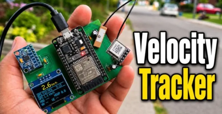
That brief does not survive jumper wire. The ATGM336H talks UART. The IMU and the 0.96" SSD1306 share I2C. Acceleration integrates at about 100 Hz, so every millivolt of supply bounce becomes a fake shove. A 2-layer board with local decoupling, a rigid IMU seat, and short bus runs is what turns a fusion sketch into something you can take outside. The earlier Arduino GPS speedometer on the same channel was "not too good." GPS is stable and slow. The MPU6050 is fast and drifts the moment you integrate it. Firmware refuses to pick a winner. A two-state Kalman filter keeps vehicle speed and a residual forward-acceleration bias. GPS remains the absolute reference. The IMU only predicts between fixes. If the inertial guess walks away, the filter re-anchors instead of arguing with the satellite.
This is a familiar class of first-article work for B2B electronics engineers: a teaching platform that still has to leave the bench, a mixed UART-plus-I2C layout that cannot invent motion, and a 2-layer FR-4 file that CAM will not have to invent holes for.
What This Video Covers
The video walks the project from the GPS-only limitation to a GPS-aided dead-reckoning speedometer on a custom double-sided board. It covers ESP32 plus ATGM336H speed measurement, MPU6050 accelerometer and gyroscope capture, GPS-aided dead reckoning, Kalman-filter-based speed estimation, automatic MPU6050 startup calibration, gravity compensation, GPS correction and re-anchoring, and the zero-velocity update that pulls the estimate to zero when the board is parked. It also shows the OLED layout that sells the instrument: a large km/h value on top, then fix, satellites, raw GPS speed, heading, HDOP, and North/East components, plus the fault strings GPS NOT DETECTED and IMU NOT DETECTED.
On the hardware side, the video is the proof that the EasyEDA 2-layer file survived first-article fab. UART2 runs GPS TX to GPIO16 and RX to GPIO17. I2C on GPIO21/22 serves MPU6050 at 0x68 and SSD1306 at 0x3C. Female headers keep the ESP32 and OLED removable. Ceramics sit on the supply pins. The GPS antenna needs sky. The IMU needs a stiff seat. Walking clips and a dashboard comparison against a car speedometer close the loop: typical gap 1–2 km/h at lower speeds and 3–4 km/h near 80 km/h.
Project Highlights and Key Features
- GPS-aided dead reckoning instead of raw NMEA speed. GPS anchors the number; the IMU makes it feel instant between sentences.
- Two-state Kalman filter for scalar speed plus residual forward-acceleration bias. The inertial path predicts; GPS corrects; the filter does not treat course as a walking-speed state.
- Startup discipline that matches a field instrument. The board sits still for a few seconds while the ESP32 averages gyroscope zero-rate bias and initializes roll and pitch from gravity.
- Mechanical rule that firmware cannot fix later. Mount the MPU6050 so +X points forward, +Y left, +Z up, and do not let the module rock on header pins. Pitch knocks gravity out of the forward axis.
- Fast-rotation suppress above about 30 dps so a yaw flick does not become a phantom sprint.
- Zero-velocity update when GPS speed, gyro rate, and acceleration magnitude all look parked for about 700 ms. That is why the OLED drops to ~0 km/h when you stop.
- Compact 2-layer standard FR-4, 1.6 mm class, 1 oz copper both sides, lead-free HASL for first articles, through-hole plus female headers.
- Local power that matches 100 Hz integration: 10 µF bulk plus 100 nF at the rails, ceramics within 2–3 mm of each 3.3 V pin.
- Front-side placement of all critical modules so an evening of soldering is enough, with a path to swap the ESP32 or OLED without respinning copper.
- Road-test honesty. Walking at 3–8 km/h, the fused number tracks pace that raw NMEA smears. Beside a car speedometer the gap stays in the low single-digit km/h range.
Challenges Encountered During Development
Fusion fails in two boring ways before it fails in math. First, the IMU is not rigid. A module that leans when you tap the OLED changes the gravity estimate, and the Kalman bias learns the wrong number. Second, GPS UART and I2C share a small board with an ESP32 radio. Without 100 nF at the pins, a Wi-Fi burst looks like a shove. The creator soldered electrolytics and ceramics on the supply islands for that reason.
Firmware also refuses heroics. GPS course is noisy when you walk, so heading stays on the OLED rather than entering the speed state. Inertial prediction is capped to a few seconds after the last GPS correction. ZUPT runs only when three sensors agree the board is still. Those software limits only work if the copper does not invent acceleration in the first place.
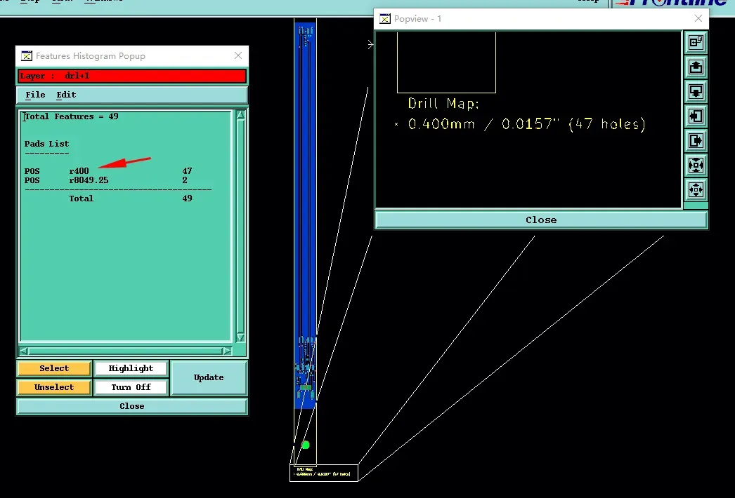
Then the Gerber raises factory questions that compact through-hole boards with headers near the outline fill every week. Via tenting on the quote disagrees with the mask layer. Header holes never declare PTH or NPTH. Tooling features arrive without a size. An antenna cutout is left for the factory to guess from the outline. On similar 2-layer PCB DFM files AIVON has reviewed, tented 0.4 mm vias could not hold the aspect ratio, NPTH sizes were missing, and a single-piece note left no locating holes. CAM had to open via drill, name the large holes, and add locating and stamp holes. The same conversation applies here: match quote tenting to the mask, open every barrel you intend to wet, keep silk off pads, and hold copper about 0.2 mm off a routed outline.
Timeline pressure sits under those DFM items. A teaching dead-reckoner that stays on jumper wire never gets the walking clip or the dashboard comparison. The idea goes cold while the filter is still being argued with. Rapid PCB manufacturing is not a slogan on this project. It is the difference between a fusion notebook and a number you can watch on the road.
How AIVON PCB Helps
The Gerbers left EasyEDA and landed at AIVON as a first-article job, not as a science project. Three days later the boards were on the bench: 2-layer FR-4, 1.6 mm class, lead-free HASL, double-sided, clean mask, holes that matched the 3D view. That turnaround is what let How To Electronics leave the jumper phase while the firmware was still in motion. The walking clip and the dashboard comparison only exist because a finished panel arrived before the idea went cold.
What the AIVON PCB actually unlocked is specific. UART from the ATGM336H no longer hops three jumper colors, so NMEA edges stay on GPIO16/17 instead of on a floating wire. The MPU6050 and the SSD1306 share one I2C pair with a fixed pull-up length, which is why 0x68 and 0x3C keep answering instead of vanishing when the OLED is replugged. Each 3.3 V island has a 10 µF bulk and a 100 nF ceramic where the current loop is small. At 100 Hz that is the difference between acceleration and supply bounce. Female headers on the ESP32 and the display made an evening assembly realistic and still left a path to swap a module. None of those features is exotic. All of them have to be true on the same piece of FR-4 or the Kalman spends the road test learning USB noise.
Conclusion
The build holds together because How To Electronics treated the PCB as part of the instrument, not as a way to hide wires. The ESP32 still does the clever work—TinyGPSPlus, the tilt filter, the two-state speed Kalman, ZUPT—but the AIVON board is what lets a 100 Hz IMU sit next to a UART GPS without inventing acceleration. Short I2C, ceramics on the pins, a stiff MPU6050 seat, and a 2-layer file that CAM will not have to argue with are the habits that make the OLED number worth watching.
The design remains a learning platform, not a certified odometer. That is the right scope. Take the fusion and the DFM discipline to the next prototype that has to leave the bench: name every hole, match tenting to the mask, keep silk off pads, put 100 nF on the IMU pin, and rigid-mount the sensor so gravity stays where the filter expects it. Standard 2-layer FR-4, 1.6 mm, 1 oz, lead-free HASL, and a three-day first article are enough when those rules are true.
FAQ
Q1: Can an ESP32 GPS + MPU6050 dead-reckoner stay on 2-layer FR-4?
A1: Yes. The filter is scalar speed plus bias, not a full INS. Two layers with local ceramics and a rigid IMU beat jumper-length I2C on four layers. AIVON PCB prototyping on standard 1.6 mm FR-4 with 1 oz copper is the right first-article stackup for this class of board.
Q2: Why place 100 nF at the MPU6050 instead of one bulk capacitor on the rail?
A2: Integration at about 100 Hz turns supply bounce into fake velocity. A ceramic within 2–3 mm of the module pin keeps the current loop small. Bulk 10 µF still belongs on the island; it does not replace the pin-level ceramic.
Q3: How should header and antenna holes be called out on a module board like this?
A3: Name PTH versus NPTH in the drill chart, size every large hole, and open the mask on barrels you intend to solder. Do not leave an antenna cutout for the factory to guess from the outline. AIVON CAM treats unnamed holes as a first-article risk.
Q4: Does the quote "via tenting" box have to match the Gerber mask?
A4: Yes. If the order says tented and the mask leaves windows, lead-free HASL will fill or leave the via on its own terms. Match one rule in the fab notes and in the mask layer before you send Gerbers.
Q5: Why does factory silk still matter on a through-hole 2-layer board?
A5: Operators solder what they can read, and ink on a pad will not wet. Keep RefDes beside the pad, copper at least 0.2 mm off a routed outline, and headers away from flooded mask. Those DFM checks are what let an evening assembly match the 3D view.
Hi everyone. Welcome to How To Electronics. Let me start with a simple question. If your car already has a speedometer, why would you build another one? Because this little board is doing something more interesting than simply reading GPS speed. It is trying to estimate velocity using GPS-aided dead reckoning.
In simple words, dead reckoning means using the motion of the device to predict how its speed is changing between GPS updates. One sensor gives us the long-term truth, while the other helps fill in what happens in between. And that is where this project gets interesting.
For this build, I used an ESP32, an ATGM336H GPS module, an MPU6050 accelerometer and gyroscope, and a tiny 0.96-inch OLED display. The GPS gives the system an absolute speed reference, while the MPU6050 reacts to acceleration almost immediately. The ESP32 combines both, so the device can keep predicting its motion between GPS measurements, then use the next GPS update to correct that prediction before the error grows too far.
At first, this sounds easy. Read GPS speed, integrate acceleration, and combine the two. But during testing, I found something much more interesting. GPS was stable but slow to react. The MPU6050 was fast, but tiny errors could build up. So, I redesigned the logic around one rule. GPS must remain the absolute speed reference, and the IMU should only help predict what happens between GPS updates. Let's build it and see how well that works in the real world.
The PCB used in this project is sponsored by Aivon, a global leader in PCB manufacturing and assembly. Aivon provides high-quality PCBs with fast production and delivery times. For new users, you can get PCB at $1 and PCBA service as low as $35 only and with free shipping.
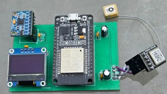
Welcome back again. The hardware is surprisingly simple. We need an ESP32 as the main controller, an ATGM336H GPS module with its antenna, an MPU6050 6-axis IMU, and a 0.96-inch SSD1306 OLED display. I also used 10-microfarad and 100-nanofarad capacitors around the power section. That is enough to build a compact standalone velocity tracker.
Here is the circuit diagram. The ATGM336H communicates with the ESP32 through UART with GPS TX connected to GPIO 16 and the ESP32 TX line on GPIO 17. The MPU6050 and OLED share the I2C bus using GPIO 21 for SDA and GPIO 22 for SCL. One serial sensor, two I2C devices, and the ESP32 doing all the processing.
After designing the schematic, I converted it into a compact PCB layout. All the main components are placed on the front side, so the complete system remains easy to assemble and test. Here is the 2D view of the board from the front side and also from the back side. Similarly, here is the 3D view of the board. The 3D view looks awesome, so the next step is to order the PCB.
The Gerber files were generated and uploaded to Aivon. Uploading the Gerber file is simple. Just select the board parameters like material, thickness, solder mask, color, and quantity. And here you can see the total quote of just $1. Shipping is also free. If you want to order a PCB for just $1, check the first link in the description.
I placed the order and within a few days I received these high-quality PCBs. The finish, silk screen, and through-hole plating were excellent.
Next, I soldered the required components and installed the ESP32, OLED display, MPU6050, and GPS module on the board. The assembly was straightforward and the completed board looks compact and professional. After connecting the GPS antenna, I powered the circuit through the ESP32 USB connector. The ESP32 power LED turned on and the OLED started the initialization sequence, confirming that the hardware was ready for testing.
The program is written in C++ using Arduino IDE. TinyGPS++ decodes the GPS data, Wire handles the MPU6050 and OLED communication, and Adafruit GFX with Adafruit SSD1306 drives the display. The MPU6050 is sampled at about 100 Hz, so the ESP32 can see motion much faster than the GPS alone. I stopped making the main speed depend on north-east integration and heading. Instead, the final version uses a scalar Kalman speed filter.
Once the code is uploaded, the OLED becomes the little dashboard for the whole system. The large yellow number at the top is the filtered velocity. Under it, we can see GPS fix, satellite count, raw GPS speed, heading, HDOP, and the north and east velocity components. I kept the raw GPS speed visible on purpose because during testing, it lets us watch the filtered value and the satellite value side by side.
Now, it was time for testing. So, I went outside my home for testing. First, I powered on the device using the power bank and waited for the device to acquire GPS fix. Finally, it was fixed in 2 minutes.
The first real test was simple. I started walking. Depending on my pace, I was seeing roughly 3 to 8 km/h. When I walked faster, the number increased. When I slowed down, it followed. And the important part, when I stopped, the filtered velocity came back to zero instead of slowly drifting away. That was a good sign, but walking speed was not going to tell me what happens at 30, 50, or 80 km/h.
So, the next test was much more interesting. I powered the board from a power bank, put it right beside the speedometer on my car dashboard, and started comparing the two displays in real time. Now, there was nowhere for the project to hide. The car dashboard was the reference I could see instantly and the little OLED had to keep up.
At around 30 kilometers per hour, the result was already very close. Then I moved into the 40 to 50 kilometer per hour range and the reading became very stable. I pushed the test to around 60 kilometers per hour and finally up to about 80 kilometers per hour. The most satisfying part was that the speed stayed controlled through acceleration, braking, and direction changes. No runaway value, no sudden jump to an impossible speed just because the device turned.
The comparison also showed something you can see instantly. At lower speeds, the difference was usually around 1 to 2 kilometers per hour and at higher speeds around 3 to 4. The GPS may react slower, but it gives the long-term reference that keeps the IMU from drifting away.
And that is really the story of this project. GPS is stable but slower. The MPU6050 is fast but cannot be trusted forever.
That's all from the video part today. The complete bill of materials, schematic, PCB Gerber file, source code, circuit explanation, and testing details are available in the How To Electronics website article. If you like this project and the journey behind making the sensor fusion work, drop a like and subscribe. Thank you so much for watching and I'll see you in the next video.





