










ESP32 Live Flight Radar: PCB Choices for Smooth Real-Time Tracking
Key Moment
- 0:00 Introduction – Upgrading to 7-inch Touch Display
- 0:29 Hardware Overview (Elecrow CrowPanel)
- 0:54 Firmware Development & SquareLine Studio
- 1:18 Flashing the Firmware
- 1:43 AIVON PCB Sponsorship
- 2:21 Wi-Fi Configuration
- 2:52 Getting OpenSky Network API Key
- 3:13 Uploading Credentials & Going Live
- 3:42 UI Overview – Radar, Flight List & Details
- 4:51 Settings & Outro
Project Background
There's something quietly addictive about a dedicated radar sitting on a desk, painting real aircraft as they move overhead. No phone, no browser—just a 7-inch capacitive screen with an animated sweep, predicted tracks, and enough detail to satisfy a plane-spotter. That's exactly what Tech Talkies delivered in Version 2 of their Flight Radar project: an ESP32-S3 running LVGL, pulling live data from the OpenSky Network API, and driving a carefully chosen HMI module that behaves like a finished instrument rather than a weekend experiment.
The creator wanted more than another app tab. He wanted a self-contained device that felt intentional—smooth movement between API updates, clean aircraft selection, on-device Wi-Fi and credential setup, and a UI that stayed responsive under continuous load. As any factory engineer who has watched hundreds of maker ideas cross the line from prototype to something people actually leave running knows, the software can be brilliant, but only a well-executed PCB keeps the display stable, the RF clean, and the power quiet while all that clever code is running. This project sits at the intersection of maker creativity and professional manufacturing discipline—the exact space where many ambitious ESP32-S3 HMI designs succeed or fail.
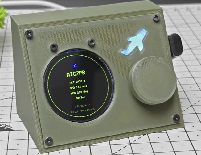
What This Video Covers
In the video, Tech Talkies walks through the complete Version 2 build of the live flight radar on the Elecrow CrowPanel Advance 7-inch ESP32-S3 HMI (V1.2) featuring the ESP32-S3-WROOM-1-N16R8 module. Viewers see the custom LVGL radar view with its living animated sweep, heading indicators, selectable targets, and detail screens that display callsign, altitude, speed, heading, country, and category. The video also covers the on-device Wi-Fi credential and radar-center coordinate setup stored in NVS, the FreeRTOS task structure that keeps network, UI, and prediction engine from interfering with one another, and the practical hardware realities of driving a parallel RGB interface while maintaining clean Wi-Fi performance.
Alongside the polished demo, the video and accompanying discussion surface real-world feedback that arrived after the release: hardware version mismatches that produced black screens, requests for adjustable range, accessibility needs for gloved hands, coverage limitations of pure OpenSky data, and even semantic debates about calling the device a "radar."
Project Highlights and Key Features
- Live aircraft data pulled from the OpenSky Network over Wi-Fi, with firmware prediction that keeps icons gliding smoothly between API updates.
- Custom LVGL radar visualization featuring an animated sweep, heading indicators, optional labels, and previous/next selection that highlights the active target.
- Full touchscreen detail view showing callsign, altitude, speed, heading, country, and category without leaving the device.
- Completely on-device configuration: Wi-Fi credentials, OpenSky API keys (uploaded once via a simple web page), and radar center latitude/longitude—all stored reliably in NVS.
- Hardware foundation of the CrowPanel Advance 7-inch ESP32-S3 HMI with 16 MB flash, 8 MB PSRAM, dual-core 240 MHz operation, and a slim 3D-printed case.
- Software stack of ESP-IDF, LVGL 8, SquareLine Studio, and carefully scheduled FreeRTOS tasks that preserve UI responsiveness under continuous display refresh and network polling.
- Version 2 focus on smoother tracking and a completely redesigned interface that makes the unit feel like a small professional instrument rather than a prototype.
Viewers' Challenges Encountered During Development
Even with a commercial HMI module as the starting point, the project revealed the classic stresses that appear once firmware leaves the creator's bench. Parallel RGB interfaces consume large numbers of GPIOs and demand short, well-referenced traces. PSRAM must sit close with clean power. Backlight current peaks and Wi-Fi TX bursts must be locally decoupled so neither starves the other. Incomplete ground planes or weak power delivery quickly appear as flicker, touch glitches, or dropped aircraft—problems no amount of firmware tuning can fully hide.
After the video dropped, real-user friction surfaced immediately: black-screen failures caused by using non-Advanced CrowPanel boards, hardcoded range that could not be adjusted from the UI, requests for a physical rotary encoder because capacitive touch fails with gloves, limited OpenSky coverage in some regions that prompted questions about adding an RTL-SDR ADS-B receiver, and even objections that the device should not be called a "radar" because it has no antenna. Hardware version compatibility, mechanical accessibility, data-source limitations, and precise RF/layout discipline all became practical challenges that any custom ESP32-S3 radar board must solve if it is to remain reliable for months of continuous desk operation.
How AIVON PCB Helps
The commercial module proved the concept, but the reliability and polish visible in the final device are exactly the outcomes that professional PCB manufacturing makes repeatable. When a maker wants the same performance in a custom form factor—or wants to push the roadmap toward an external ADS-B receiver, battery power, adjustable range, aircraft trails, or offline mode—they need a partner who treats the board as an engineering collaborator rather than a commodity.
AIVON's process removes the usual friction of shopping multiple fabs through instant quoting after Gerber upload. More importantly, the engineering review before production catches the exact issues that kill ESP32-S3 HMI projects: incomplete ground planes under the RGB bus, insufficient copper for backlight and Wi-Fi TX peaks, antenna keep-out violations, missing stitching vias, and silkscreen or soldermask problems around fine-pitch WROOM footprints. Those checks are the difference between a board that works on the first power-up and one that needs a respin after the firmware is already written.
For a project like this Flight Radar the practical advantages appear in three concrete ways. First, proper stack-up and material selection (4-layer FR-4, Tg 130–150 °C, 1.6 mm, continuous ground under RGB and RF) deliver the thermal stability and clean return paths needed inside a closed 3D-printed case while the display refreshes continuously and Wi-Fi polls. Second, DFM optimizations and manufacturing precision ensure the fine-pitch module, display connector, and power path remain consistent unit to unit, so the same firmware behaves identically on every board. Third, responsive engineering support means layout feedback arrives while the design is still flexible—allowing an external antenna connector, battery charging path, or extra I/O for future sensors without delaying the next revision.
In short, AIVON turns an ambitious idea into hardware that actually delivers the experience the creator imagined by combining rapid PCB prototyping, expert DFM analysis, high-quality fabrication, and reliable delivery into a one-stop solution.
Conclusion
Tech Talkies took a clear idea—live aircraft on a dedicated touchscreen—and turned it into an open-source instrument that is genuinely pleasant to leave running on a desk. The prediction layer, the animated sweep, the touch interaction, and the clean configuration flow are the visible achievements. The invisible ones are the board-level decisions that keep those features stable for hours at a time.
Whether you stay with an off-the-shelf HMI or decide to design your own version with extra sensors, battery power, or a different enclosure, the same principles apply: solid ground planes, careful RF layout, robust power delivery, and a manufacturing partner who reviews the design before copper is etched. That combination is what turns a weekend prototype into something you can trust.
If a similar project is sitting in your head, start with the open-source firmware and 3D case files linked from the video. When you are ready for boards that match the ambition of the software, bring AIVON into the loop.
FAQ
Q1: Why does a software-heavy ESP32-S3 flight radar still need careful PCB design?
A1: The parallel RGB interface, continuous PSRAM traffic, Wi-Fi bursts, and capacitive touch all share the same copper. Incomplete grounds or weak power delivery appear as flicker, touch glitches, or dropped aircraft—problems that firmware alone cannot fully hide.
Q2: Is a 2-layer board realistic for an 800×480 ESP32-S3 radar with parallel RGB?
A2: For simple SPI screens, yes. For parallel RGB plus simultaneous Wi-Fi, a 4-layer board with a continuous ground plane is the practical minimum. The extra layers provide clean return paths at still-reasonable prototype cost.
Q3: What is the most common layout mistake when adding an external ADS-B receiver later?
A3: Violating RF keep-out zones or breaking the ground plane between the ESP32 module and the new antenna section. Early manufacturing review that flags copper pours and via placement prevents range and interference surprises.
Q4: How much does surface finish matter for a small-batch or reworkable ESP32-S3 board?
A4: ENIG or high-quality HASL delivers reliable joints on the fine-pitch WROOM and any expansion connectors. It also tolerates multiple reflow or hand-soldering cycles better while the design is still iterating.
Q5: Can professional manufacturing help even if I only need a handful of boards?
A5: Yes. Instant quoting, engineering DFM checks, and quick-turn fabrication catch missing stitching vias or thin copper on the backlight rail before the first article is made—saving far more time than the service costs.
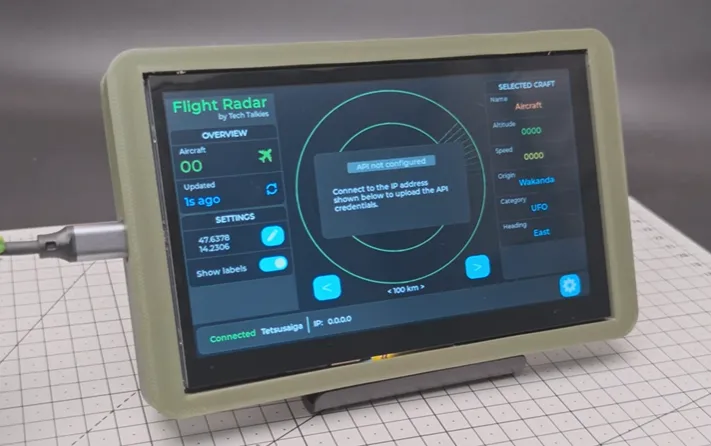
Hello fellow makers. We recently made this flight radar on our channel, but some of you asked for a bigger screen and more features. So, we are upgrading the flight radar onto a 7 in touch display. And for this, we'll be using the Elecrow CrowPanel 7in advanced display. It is a 7-in capacitive touchscreen display powered by an ESP32 S3 chip. and I've 3D printed the simple case for it. It is slim and fits perfectly.
So, I'm in the process of making the firmware for this and I thought I'll give you guys an update on how it's going. I've designed the UI in SquareLine Studio. and it is exported directly into my ESP-IDF project. The code is still a work in progress, so it will not be open source immediately, but I will make it open source once I feel like it is complete or if the video hits 25,000 views, whatever comes first. But you can still get the firmware by going onto the Tech Talkies flasher page and directly flashing it onto your display.
Once you have flashed the firmware onto the display, you are ready to configure it.
And if you need a custom PCB for a project, Aivon is a one-stop PCB manufacturing and assembly service. So you can go from design to fully assembled board without juggling multiple vendors. Ordering is also pretty straightforward. You can go to their website, upload your Gerber files, select your board specs like thickness, layers, and quantity, and you'll get an instant quote. From there, you can place your order, track the progress online, and they handle the rest, including fabrication, and even assembly if needed. They support everything from quick prototypes to full production runs. If you want to try it out, I have left the links in the description. Go check them out.
First thing is to connect it to a Wi-Fi network. So when it boots and is not connected to any Wi-Fi networks, it will show you a list of Wi-Fi networks. So you select a Wi-Fi network on the left side and enter the password for it on the right side and click on connect. Once it is connected to the network, it will open the radar page. And here you can see that you need an API key from OpenSky network.
To get the key, go to the OpenSky network web page. Link is in the description and sign up for a free account. Once you have signed up and logged in, go into your accounts page and create a free API key and download the file.
Next, using any other device on the same network as your display, open the IP address of the display, which is shown at the bottom of the screen here. And here you can upload the credential files you just downloaded. So, select the file and upload it. Once it's uploaded, the display should refresh and our radar is live.
Let me tell you a little bit about the user interface here. So obviously that is the radar and on the left side panel we have the number of flights currently in our radar system and how long ago the data was updated from the API. And here you can edit the coordinates of the radar. You can change it by clicking on the edit button and entering your latitude and longitude here. And next, you can turn off the labels for the flights. And these buttons, the left and right buttons, you can use to select the flight to see the information on the right side panel. And at the bottom of the screen is the status bar where you can see the status of the Wi-Fi connection. Here we are connected to the network name here and the IP address of the display device. Next, there is a settings button. For now, this only has two settings, which is forget Wi-Fi and forget API key. If you have a problem with the connected Wi-Fi network or you just want to connect another network, you can click on forget Wi-Fi and you will get the Wi-Fi configuration page.
Again, that is all for our flight radar. I have built this from scratch and I would appreciate uh if you can give me your feedback or try this firmware. Uh I will make it open source once it is ready to go and I would appreciate any changes or comments there too.
Until then keep making.





