There's something quietly addictive about a dedicated radar sitting on your desk, painting real aircraft as they move overhead. No phone, no browser—just a 7-inch capacitive screen with an animated sweep, predicted tracks, and enough detail to satisfy a plane-spotter. That's what Tech Talkies delivered in Version 2 of their Flight Radar: an ESP32-S3, LVGL, the OpenSky Network API, and a carefully chosen HMI module that behaves like a finished instrument.
The creator wanted more than another app tab. He wanted a self-contained device that felt intentional—smooth movement between API updates, clean aircraft selection, on-device Wi-Fi and credential setup, and a UI that stayed responsive under continuous load. As a factory engineer who has watched hundreds of maker ideas cross the line from prototype to something people actually leave running, I always look at the board underneath. The software can be brilliant, but only a well-executed PCB keeps the display stable, the RF clean, and the power quiet while all that clever code is running.
A Desk Instrument Instead of Another App Tab
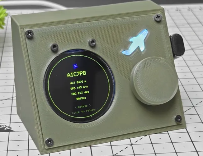
Live aircraft data arrives from OpenSky over Wi-Fi. Between updates the firmware predicts position so the icons keep gliding. A custom LVGL radar view draws the sweep, headings and selectable targets. Touch the screen and you can step through flights, pull up callsign, altitude, speed, heading, country and category, then drop back to the scope. Wi-Fi credentials and the radar's center coordinates live in NVS so the unit wakes up ready to work.
Hardware is the Elecrow CrowPanel Advance 7-inch ESP32-S3 HMI (V1.2) with the ESP32-S3-WROOM-1-N16R8—16 MB flash, 8 MB PSRAM, dual-core 240 MHz. A slim 3D-printed case finishes the look. Everything runs under ESP-IDF with LVGL 8 and SquareLine Studio. Version 2 focused on smoother tracking and a completely redesigned interface, and the result feels closer to a small instrument than a weekend experiment.
What sells the experience is the prediction layer and the touch interaction. The radar never freezes waiting for the next API packet, and selecting an aircraft feels immediate. Those moments only stay reliable when the PCB underneath can feed the parallel RGB interface, keep PSRAM traffic clean, and let Wi-Fi coexist with continuous display refresh.
The Moments That Make the Radar Feel Alive
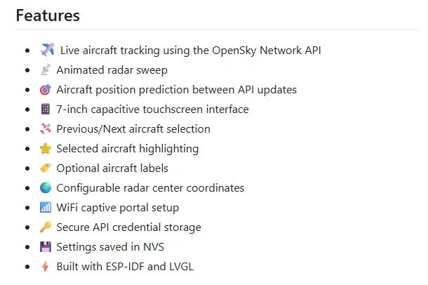
The animated sweep is the first thing that catches the eye. It is not just decoration; it gives the display a living rhythm. Aircraft icons carry heading indicators and optional labels. Step through the list with Previous/Next controls and the selected target is highlighted so you never lose it in a busy sky. Open the detail screen and the data is clear and complete—exactly what a spotter wants without switching devices.
Wi-Fi setup happens entirely on the touchscreen. Choose the network, type the password, save, and the credentials stick. OpenSky API keys are uploaded once through a simple web page served by the device and then locked safely in NVS. Radar center latitude and longitude are adjusted the same way. The whole configuration flow is designed so a non-engineer can get the unit running without a serial console.
Figure:Wi-Fi setup and OpenSky API keys
All of this runs on FreeRTOS tasks that keep the network, the UI and the prediction engine from stepping on each other. The smoothness you see on screen is the visible result of that careful scheduling—and of a board that does not introduce extra noise or voltage dips while the tasks are running.
What the Board Under the Glass Actually Has to Deliver
Even though this build started with a commercial HMI module, the design rules that make it work are the same ones any custom ESP32-S3 radar board needs. A typical high-performing layout looks like this:
|
Parameter |
Practical Target |
Why it matters here |
|---|---|---|
|
Layers |
4-layer |
Continuous ground under RGB and RF |
|
Material |
FR-4, Tg 130–150 °C |
Stability inside a closed 3D-printed case |
|
Thickness |
1.6 mm |
Rigidity for the large panel and mounting |
|
Copper |
1 oz outer / 0.5–1 oz inner |
Handles backlight peaks and Wi-Fi TX current |
|
Surface finish |
ENIG or quality HASL |
Reliable joints on the fine-pitch WROOM |
|
Vias |
Through-hole + selective microvias |
Dense routing around the module without signal degradation |
|
RF keep-out |
Strict around the antenna |
Preserves range while the display is refreshing |
The parallel RGB interface eats a large number of GPIOs and demands short, well-referenced traces. PSRAM must sit close with clean power. Backlight and RF sections need their own local decoupling so neither starves the other. These details are the difference between a radar that stays smooth for hours and one that occasionally glitches when the Wi-Fi radio transmits.
What Viewers Actually Ran Into After the Video Dropped
The polished build in the video is only half the story. Once people started flashing the firmware themselves, the comments revealed the real-world friction that every open-source hardware project eventually faces.
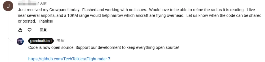
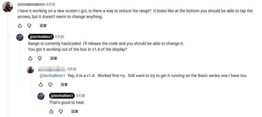
One of the most common requests was range control. A viewer got the radar working on a new v1.4 screen and immediately asked whether the bottom arrows could reduce the range—nothing seemed to change. Tech Talkies replied that range is currently hardcoded and would become adjustable once the code was released. The same viewer confirmed the Advanced series board worked first try, then mentioned plans to try the Basic series version as well. Hardware version differences quickly became a recurring theme.
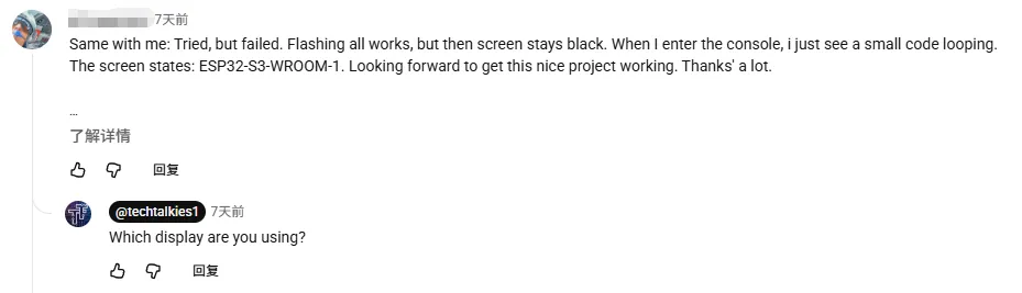
Black-screen failures appeared next. Several people reported that flashing succeeded but the display stayed black, with only a short code loop visible in the console and the text "ESP32-S3-WROOM-1" on screen. In every case the root cause was the same: they were using a non-Advanced CrowPanel. Tech Talkies asked for the exact board version, confirmed the mismatch, and later open-sourced the full code so others could adapt it.
Accessibility came up in a thoughtful exchange. A viewer asked whether the rotary encoder from an earlier project could be added as a backup, because gloves often fail on capacitive touch. The initial reply was skeptical—"when would you need a knob if you can touch the screen?"—but the follow-up explanation about daily soldering and gloved hands immediately changed the tone. Tech Talkies agreed a physical knob would be a worthwhile addition.
Coverage limitations of OpenSky also surfaced. One commenter asked about adding an RTL-SDR for direct ADS-B reception because OpenSky coverage is poor in their area. The honest answer was that the creator does not currently have access to an ADS-B module, though others have already demonstrated it is possible.
Finally, a semantic objection arrived: the project should not be called a "radar unit" because it has no antenna and simply displays data pulled from the network. Tech Talkies acknowledged the point and clarified that it is a simple desktop display of live flight data—nothing more, nothing less.
These comments are the practical challenges that appear once a project leaves the creator's bench: hardware version compatibility, hardcoded parameters, accessibility for gloved or dirty hands, data-source coverage, and even how the project is described. They are also the exact reasons a clean, well-documented board design and open-source release matter.
How AIVON's PCB Approach Actually Helped This Project Succeed
This is the part that often gets understated. The commercial module proved the concept, but the reliability and polish you see in the final device are exactly the kind of outcomes that professional PCB manufacturing makes possible. Tech Talkies explicitly points makers toward AIVON in the video for a reason: when you want the same level of performance in a custom form, or when you want to push the roadmap (ADS-B receiver, battery power, adjustable range, aircraft trails, offline mode), you need a partner who treats the board as an engineering partner rather than a commodity.
AIVON's contribution is not abstract. Instant quoting after Gerber upload removes the usual friction of shopping multiple fabs. More importantly, the engineering review before production catches the exact issues that kill ESP32-S3 HMI projects: incomplete ground planes under the RGB bus, insufficient copper for backlight and Wi-Fi TX peaks, antenna keep-out violations, missing stitching vias, and silkscreen or soldermask problems around fine-pitch WROOM footprints. Those checks are the difference between a board that works on the first power-up and one that needs a respin after the firmware is already written.
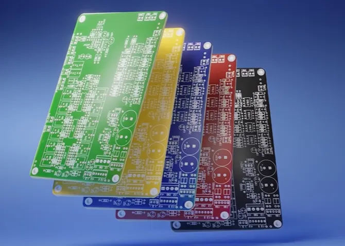
For a project like this Flight Radar, the practical advantages show up in three concrete ways:
● Stack-up and material selection give a continuous ground plane and the thermal stability needed inside a closed 3D-printed case. That directly supports the continuous display refresh + Wi-Fi polling that the prediction engine relies on.
● DFM optimizations and manufacturing precision ensure the fine-pitch module, the display connector and the power path are consistent across boards. Unit-to-unit variation disappears, so the same firmware behaves the same way on every unit—an essential requirement once you move past a single desk prototype.
● Responsive engineering support means layout feedback arrives while the design is still flexible. When a maker wants to add an external antenna connector for better range, a battery charging path, or extra I/O for future sensors, the feedback arrives early enough that the next revision still ships on schedule.
In short, the commercial module showed what is possible. AIVON's process is what lets a maker take that same level of performance, make it custom, make it repeatable, and make it ready for the next set of features on the roadmap. The radar feels solid because the board underneath was treated with the same seriousness as the software. That is how AIVON helps: by turning an ambitious idea into hardware that actually delivers the experience the creator imagined.
DFM Checklist Tailored to ESP32-S3 Desk Radar Boards
|
Check Item |
Why It Matters |
Pass Criteria |
|---|---|---|
|
Continuous ground under RGB / high-speed buses |
Keeps display and RF quiet |
No splits under critical traces |
|
Strict RF antenna keep-out |
Maintains range while the screen is busy |
Clear copper and components per module rules |
|
Local decoupling for module + backlight |
Survives TX peaks and current spikes |
Bulk + ceramics within a few mm |
|
Via stitching around RF and power |
Improves return paths and reduces EMI |
Dense stitching on ground planes |
|
Mechanical support for the large panel |
Survives handling and thermal cycles |
Mounting holes and optional stiffener |
|
Power-rail copper and regulation |
Prevents brown-outs during simultaneous loads |
Adequate width and clean 3.3 V / 5 V delivery |
What Stays with You After the Sweep Fades
Tech Talkies took a clear idea—live aircraft on a dedicated touchscreen—and turned it into an open-source instrument that is genuinely pleasant to leave running on a desk. The prediction, the sweep, the touch interaction and the clean configuration flow are the visible achievements. The invisible ones are the board-level decisions that keep those features stable for hours at a time.
Whether you stay with an off-the-shelf HMI or decide to design your own version with extra sensors, battery power or a different enclosure, the same principles apply. Solid ground planes, careful RF layout, robust power delivery, and a manufacturing partner who reviews the design before copper is etched will always matter more than the latest library version. That combination is what turns a weekend prototype into something you can trust.
If a similar project is sitting in your head, start with the open-source firmware and the 3D case files. When you are ready for boards that match the ambition of the software, bring AIVON into the loop. The aircraft will still be flying; the only question is whether your radar will still be tracking them cleanly months later.
FAQ
Q1: Why does a software-heavy project like this still need careful PCB design?
A1: The parallel RGB interface, continuous PSRAM traffic, Wi-Fi bursts and capacitive touch all share the same copper. Incomplete grounds or weak power delivery show up as flicker, touch glitches or dropped aircraft—problems that no amount of firmware tuning can fully hide.
Q2: Is a 2-layer board realistic for an 800×480 ESP32-S3 radar?
A2: For simple SPI screens yes. For parallel RGB plus simultaneous Wi-Fi, a 4-layer board with a continuous ground plane is the practical minimum. The extra layers give clean return paths at still-reasonable prototype cost.
Q3: What is the most common layout mistake when adding an external ADS-B receiver later?
A3: Violating RF keep-out or breaking the ground plane between the ESP32 module and the new antenna section. A quick manufacturing review that flags copper pours and via placement early prevents range and interference surprises.
Q4: How much does surface finish matter for a small-batch or reworkable board?
A4: ENIG or high-quality HASL gives reliable joints on the fine-pitch WROOM and any expansion connectors. It also tolerates multiple reflow or hand-soldering cycles better when you are still iterating the design.
Q5: Can professional manufacturing help even if I only need a handful of boards?
A5: Yes. Instant quoting, engineering DFM checks and quick-turn fabrication catch missing stitching vias or thin copper on the backlight rail before the first article is made. That saves far more time than it costs.
Q6: What material and thickness work best for a closed desk device like this?
A6: Standard FR-4 with Tg 130–150 °C and 1.6 mm thickness balances cost, rigidity and thermal performance. The board stays flat under the large panel, handles continuous operation heat, and mounts cleanly into a 3D-printed case.