










From $4 Pico to PS3 Super Slim Powerhouse: The PCB Journey Behind a qCFW Modchip Hack
Key Moment
- 0:00 Introduction – Hunting for a PS3 SuperSlim
- 1:00 Acquiring the Console & Initial Test
- 1:48 Console Already Has HEN – Firmware Check
- 2:07 AIVON PCB Sponsorship
- 2:38 Critical Warning – Backup Your Flash
- 3:09 Backing Up NOR Flash with Rebug Toolbox
- 4:23 Reinstalling HFW Firmware Twice
- 4:40 Jailbreaking Issues & Workaround
- 5:39 Preparing BadWDSD / qCFW Files
- 6:00 Installing Stage X
- 6:27 Disassembling the Console
- 6:50 Positioning the Raspberry Pi Modchip
- 7:00 Soldering CMD & Clock Points
- 7:50 Soldering Syscon RX & TX
- 8:30 Routing Wires & Securing with Tape
- 10:00 Reassembling the Console
- 12:00 First Boot & Testing qCFW
- 14:00 Final Results & Demonstration
- 16:00 Summary & Outro
Project Background
In the competitive console modding and hardware-hacking community, late-model PlayStation 3 Super Slim units (CECH-4x00 series with NOR flash) long resisted reliable custom firmware. Traditional softmods became unreliable or impossible after Sony's hardware revisions. Makers needed a persistent quasi-CFW solution that retained Cobra features, HDD key dumping, OtherOS support and a safe recovery path to official firmware—without relying on software-only exploits that could be patched.
Chase Fournier's project answered that need by pairing a stock Raspberry Pi Pico (RP2040) with the BadWDSD modchip. The result is a working qCFW (based on Evilnat PEX) that boots from NOR-stored Stagex after the Pico injects stage-entry code into XDR RAM. This video documents the full process, from verification and NOR backup through hardware installation, first successful triple-beep boot and final Evilnat logo. It is a transparent masterclass in treating high-stakes console work with professional electrical and mechanical discipline.
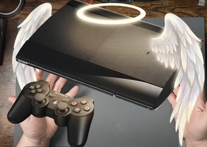
What This Video Covers
The video walks viewers through the complete workflow: console verification, Hybrid Firmware reinstall, NOR flash backup with Rebug Toolbox, PS3HEN and Stagex installation, Pico UF2 flashing, precise four-signal wiring (CMD, CLK, SC_RX, SC_TX) plus power and ground, mechanical placement near the disc-drive bay, first boot success, qCFW installation, optional LED status mod, and recovery considerations. It also shows real troubleshooting—TX/RX swaps, space constraints, resistance checks and wireless-controller quirks—leaving the mistakes in the footage so viewers understand exactly what can go wrong and how to recover.
Project Highlights and Key Features
- Minimalist yet robust interface: only CMD, CLK, SC_RX and SC_TX are required for the core exploit; HOLD, BANKSEL and DEBUG remain optional recovery and diagnostic pins.
- RP2040 injects stage-entry code into XDR RAM so the console loads Stagex from NOR, unlocking Cobra features, HDD key dump, OtherOS via petitboot and syscon access at 576000 baud.
- Electrical best practices captured on camera: 0.1 mm magnet wire for high-speed XDR signals to minimize capacitance and inductance, thicker conductors for power and ground, shortest practical runs routed away from noisy switch-mode areas, ≈55 Ω CMD/CLK-to-GND verification before power-up, and high-quality no-clean flux with thorough IPA cleaning.
- Mechanical foresight: double-sided tape mounting near the disc-drive bay, strain relief at every joint, and an optional status LED that re-purposes the standby light so the modchip state is visible without reopening the case.
- Transparent recovery path and software work-arounds that keep the console recoverable even after imperfect flashes.
These choices turn a $4 microcontroller board into a reliable gateway for features Sony never intended on Super Slim hardware.
Challenges Encountered During Development
High-speed XDR CMD and CLK lines leave almost no margin for parasitic capacitance, inductance or timing skew. Excess wire length, thicker gauge or a cold joint quickly produces XDR initialization failures (green light of death or rapid LED flash followed by shutdown). Physical space inside the Super Slim is extremely tight; even a Pico can be crushed by shell pressure if placement and wire dressing are not planned. TX/RX polarity swaps, damaged sense resistors (detectable by the 55 Ω check), flux residue on high-impedance pads, and Bluetooth controller power-cycle quirks all appeared during the build. Early firmware versions offered little diagnostic feedback, forcing iterative measurement and re-soldering. These are classic prototype-to-production issues: wire gauge selection, routing discipline, joint quality and mechanical strain relief are every bit as critical as pad size or via design on a custom board.
How AIVON PCB Helps
A hand-wired Pico is an excellent proof-of-concept, yet the jump from "works once on the bench" to "reproducible by the community with high yield" requires a purpose-designed PCB. AIVON specializes in exactly this transition. Upload Gerbers and the free engineering review immediately flags marginal pad sizes for hand soldering, suboptimal via placement, insufficient copper weight for solid 3.3 V distribution, or solder-mask openings that compromise joint strength.
Standard FR-4 with ENIG or immersion-silver finish delivers oxidation-resistant pads ideal for microscope work. Controlled-impedance routing and length-matched CMD/CLK traces eliminate the parasitic loading that causes XDR failures. Solid power and ground planes remove voltage-drop concerns under RP2040 load. HOLD, BANKSEL and DEBUG appear as clearly labeled test pads or switches. The board outline can be contoured to nest safely under the Super Slim disc-drive bay so shell pressure never becomes a risk.
Rapid prototyping lead times measured in days—not weeks—let makers order five or ten boards, validate in real consoles, refine silkscreen or add a status-LED footprint, and iterate before community interest fades. Consistent plating thickness, precise registration and 100 % electrical testing ensure every board behaves identically. Whether the design stays two-layer or later requires tighter form factors, higher-speed signals or simple HDI features, AIVON's one-stop DFM analysis, material selection and fast-turn manufacturing convert the hard-won lessons of a single successful build into reliable, shareable hardware.
Conclusion & Call to Action
Chase Fournier's transparent build demonstrates that careful electrical and mechanical decisions—not magic—unlock features on locked-down hardware. The same DFM discipline that kept the hand-wired version alive is applied systematically when the design moves to a custom PCB.
If you are designing an RP2040-based console modchip, signal-integrity critical interface board, or any compact high-speed prototype, start with professional manufacturing support. Request a free DFM analysis, upload your Gerbers, or contact AIVON today for rapid PCB prototyping and production. Turn the next ambitious idea into hardware the whole community can trust.
FAQ
Q1: Why is 0.1 mm magnet wire recommended for CMD and CLK on an RP2040 PS3 modchip?
A1: These lines carry high-speed XDR interface signals. Thicker wire adds capacitance and inductance that can push timing outside the RP2040's window. Magnet wire keeps parasitic loading minimal and electrical length short—exactly the signal-integrity practice AIVON applies with controlled-impedance traces on custom PCBs.
Q2: What surface finish and copper weight does AIVON recommend for a production modchip PCB?
A2: ENIG or immersion silver for reliable hand-soldered joints on fine pads, and 1 oz copper minimum so power distribution remains solid even on a compact board. These choices maximize assembly yield when builders use the same tools and techniques shown in the video.
Q3: How does AIVON's free DFM analysis help when converting a hand-wired Pico prototype to a custom board?
A3: The review flags marginal pad sizes, via placement that reduces yield, insufficient copper weight, and solder-mask openings that leave too little copper for solid joints—preventing the exact failure modes (XDR init errors, voltage drop, mechanical stress) that appear in hand-wired builds.
Q4: Can a custom AIVON PCB improve recovery and diagnostics compared with flying wires?
A4: Yes. HOLD, BANKSEL and DEBUG can be brought out as clearly labeled test pads or small switches, eliminating wire-guessing and allowing soft recovery without full desoldering. Length-matched traces and solid planes further increase first-boot success rates.
Q5: What lead times can makers expect for small-batch RP2040 modchip PCBs from AIVON?
A5: Days, not weeks. Rapid prototyping allows ordering five or ten boards, testing in real Super Slims, iterating silkscreen or LED footprints, and receiving revised boards while community interest is still high.
PS3 SuperSlim. So, as the start of this video, I want to install QCFW on the PS3 SuperSlim, but the problem is I don't have one. And then so began my search.
I first came across this post on Facebook Marketplace, and there is what did you think a PS3 SuperSlim? And I asked him if he'd be willing to trade for an RGH Xbox 360 cuz I conveniently have a lot of those. And unfortunately, I kind of wasted too much time cuz I was very very busy, and he has not gotten back to me. So, it's unfortunate.
Then I found this one covered in stickers. Then I was thinking to myself, "Well, why don't I message him and just see if it's possible we can pick this one up." So, then after a long conversation, I decided to offer him some of my Xbox 360s, and he seemed interested. So, then I decided, "Well, let's test a couple out and see if we can get them working." Because I mean, a lot of these consoles I own and I've worked on before and fixed or they need some work and they've been modified, etc. And some of them work completely fine, some of them have disc drive issues or don't boot or this or that. So, I have to check them out beforehand.
But then we ended up settling on $60, and he figured out exactly what model it was, and it was a CECH-4201B. So, I knew this one was going to be compatible. So, then I drove. I sat in the parking lot and I waited. And then lo and behold, he showed up. I got out of the car, I met with him, we did the exchange, and there I was with a PS3 SuperSlim in my hands. And so, I drove all the way back to the shop, a 35-minute drive. And that brings us to now. Let's test it out.
Okay, so fun fact, the PS5 controller using through the Monty boy on the PS3, and it works. And turns out the console already has HEN installed. So, this actually should be pretty pretty straightforward. What firmware are we on? 4.91. So, we're probably going to have to on a 250 gig hard drive. Nice. Okay, let's get this thing apart.
All right, so the first thing's first, we need to reinstall 4.92 HFW, which is the modified firmware for HEN, so we can jailbreak the console. But we need to install it twice because QCFW is going to ask us to reinstall the firmware. So, might as well do it twice now so we can save ourselves in the future.
Have you ever thought about making a PS3 yourself? Well, do I have the solution for you. This video is sponsored by Aivon. Aivon is a company that delivers high-quality PCBs. So, if you wanted to design your own PS3 PCB motherboard, you can technically do it through KiCad and then send it to Aivon, and then they'll make it for you. Now, because Aivon is so awesome, they're offering $60 for new users to go towards their PCB prototypes. That means literally, you can get your PCB for $1. So, consider trying Aivon today for your PCB project.
Now, I want to preface something really quick. This is super super super super important. You need to back up your flash. If you do not back it up and you brick your console for whatever reason, the lightning strikes the console and while you're installing something and the console survives but the install didn't, it doesn't matter. You need to back up your flash. If you do not back up your flash, you could brick your console permanently and that could be over for you. What we will be doing does modify the flash. So, it is super important that you back up your flash. We all know that now.
Now, we're going to back up our flash via Rebug Toolbox. So, go ahead and download the latest version of this and put the package file on the root of your USB drive. Now that we're back at the PS3, we're going to go to the our standard install location for packages and install Rebug Toolbox. Boom. Now that we have it here, let's go ahead and launch it. Now that we're in Rebug Toolbox, we're going to go over to export flash to file. This is going to be dev_usb000, and that means we're going to put the flash drive in the port closest to your disc drive like we already did before previously. We're going to go ahead and hit X on that. Yes, we want to export a flash memory to a file. Yes. All right, so it's going to going to do that. Beautiful. And Okay, okay, let's do it a second time just because we want two files. Now we have our flash memory. Okay, let's go ahead and quit Rebug Toolbox. We're going to go ahead and hook up the flash drive to the computer again. And you see these two files right here? This is your flash. Make sure you put this in a very very very safe place.
All right, now that we have all of our wires in, let's go ahead and get ready to close this thing up. But not yet cuz obviously we have to connect the Pi. But what I am looking for is to see where things are at here. I mean, I suppose if your wires are kind of going in that orientation and they're not they're not going to rub, they should be fine. Okay, perfect. Let's put the screws in. And if you haven't replaced your thermal paste, you should do it now, which I technically already did mine. So, time to connect the Pi.
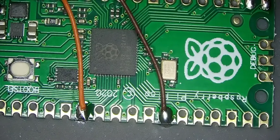
First things first, let's get the power wire soldered. Little bit of flux there. Let's add some solder, just like that. We'll turn the Pi like that. That way we can connect this wire easily. Just like that. Then we can connect our ground. Solder here. These are for our syscon. This is our receive line going to our transmit on the Pico. And then our receive line going to the transmit on the board. And then our last two. This line right here and this line right here. Now, if I remember that correctly, this is our clock and this is our CMD. Just like that.
Now, before we seal the deal, let's temporarily connect the power button. So, we want to see if this thing works before we move forward. Now, it's good to wait until this Pico goes solid cuz then it means it got a successful off. And in the event that this continues to blink E forever, which it looks like it probably will, I got these wires mixed up. So, we actually need to solder the blue one to the bottom and the yellow one to the top. Just like that. This time when we plug it back in, we should get solid LED. There it is, it's solid.
Now, let's connect the hard drive cuz this is the last thing I forgot to do. And then if everything works, we should see this beep three times and then it should show bad WD SSD detected once we get in uh jailbreak the console. Triple beep, nothing happened. Okay, I think I had the wires mixed up over here, too. Oops. Solder our orange wire and solder our brown wire. Just like that.
Now, before we test this thing, I need to see if the Pico gives a solid blink. Uh once it goes solid, we know that it got the successful off. Perfect. Let's turn it on see if it works. Got the triple beep and now we should be able to switch to the PS3's input. Okay, fantastic. It's booting up and it appears to be functional.
Now, let's go over to the egg and jailbreak the console. Welcome to PS3 hen. Perfect. And bad WD SSD has been detected. That's exactly what we want to see.
Before we officially move forward, we have to take our USB drive, put it in the USB closest to the disc drive, which is going to be this first one right here. This has our custom firmware QCFW files on it. Now, we go to hybrid firmware tools, QCFW options, install CFW. And if all is success, which it looks like it is. For my flash drive, it has a light on it, so it's going to be blinking just indefinitely for a few minutes. Probably about 10 10 11 minutes. However long it takes to install a firmware, that's what it's going to be doing. So, we're going to just let it sit and when we come back, it should be all good to go.
Okay, we just got a triple beep and the console is restarting. And here we are. QCFW on the PS3 super slim. We can even overclock. Let's see, default frequencies. Okay, let's do a custom value. Let's just go for it. The console didn't know what to do. Okay, that's funny.
Now that we've achieved QCFW, there's one more mod that I want to do while getting this thing put back together. I have my multimeter leads in diode mode. This is the power button. What I was thinking is is we could take the light that's here that's red, the standby light, and use that as the Pico light that flashes to make sure we get an off while the PS3 is closed.
Now, this is my red lead, the positive, and we got the red light lighting up when I put black probe here or we got the green light there, but we want the red one cuz the green one's going to be on kind of all the time. So, I think what we should do is we should cut this line right here. I'm assuming, right? Yeah, cut it cuz that's positive. Cut that one and then run a wire from there over there. And then if this doesn't work, maybe maybe this will automatically switch to ground to make this light active when it's off. I don't know. But, the only way to know is to to cut it and try it.
Now, the reason by which that we're cutting this trace is because I don't want the PS3 to to tell this LED what to do anymore. I want the Pico to tell this LED what to do. Don't tell me what to do. As far as the red line, so we'll just cut that. Okay, brush that away. All right. Looks like I did a pretty good job of cutting it deep enough where it's all the way through. Uh yeah, it looks like it's cut to me.
Now, we have to be super careful when doing this mod. We're just going to add a teeny teeny teeny weensy bit of flux. That's like way too much. I just want to tie literally want way less than that. I just need a little bit right over there in that area and then that's that's like it. All right, we're going to take our soldering iron very very carefully. I'm just going to touch that pad up underneath the LED. Okay. Okay. Now, very very carefully, I'm just going to touch that pad up underneath the LED. Okay.
Now, for this, I'm using a very very thin jumper wire and it's enameled, so you can touch it to things and it won't short out cuz the one thing we don't want to do is we don't want to kill this LED cuz then that would suck. Right there. Boom. And then on the Pico, we need to put a little bit of flux right there. We're going to take our soldering iron, do that. Break this LED off the board cuz we don't no longer need it. Just like that mostly. Which is what I made it a little bit of a mess. Apply a little bit of solder here. Just like that. Now, we're going to very carefully take our jumper wire. Just like that.
All right. Now, go ahead and take the Pico. Let's put our double-sided stick tape down. Put our Pico right there. Stick that. Then be very very careful with this little jumper wire. All right, let's place the button back in its little holder. Route this little wire so it's not just anywhere. The disc drive one more time came unplugged. And then let's plug it in and see if it works.
Okay, that didn't work. We still have to modify something. All right, now since we have our wire soldered there, move that. And then, last but not least, we have to cut this connection here completely. All right, and then take a little bit of flux here. That's like way too much, but that's fine. We can make it work. A little bit of solder here. Connect that to ground. Got our wire soldered there. And we'll cut the rest of the wire. Let's verify. Yep, that's good. All right, and then we'll just clean it up with the alcohol and the brush.
We got that wire soldered. So, all in all, if I plug it in, it should turn on. Let me fix the the other one. Perfect, that one's fixed. All right, so this is how I've set it up. I cut this. I cut this. I soldered the wire from the Pico here. This one's still connected and this one's still connected. There we go. Now, you won't have red, but you will have green. This mod's not for everybody, but it just looks kind of cool to me.
Okay, so as I always make corrections, um I ended up putting the Raspberry Pi right here on top of this ribbon cable cuz that was the only place. Apparently, this area right here is reserved for these gears. So, as far as I can tell, everything closes up normal. Let's check and see if it actually works. Okay, and it got the off. Triple beep.





