There's something magnetic about watching a skilled repair tech dig into a console that the manufacturer thought was locked down forever. In "The Final Hack Sony Can't Patch," Chase Fournier takes a late-model PS3 Super Slim (CECH-4x00 series with NOR flash) and turns it into a fully functional qCFW machine. He does it the hard way—openly, with mistakes left in the footage, flux fumes and all—using a Raspberry Pi Pico as the heart of the BadWDSD modchip.
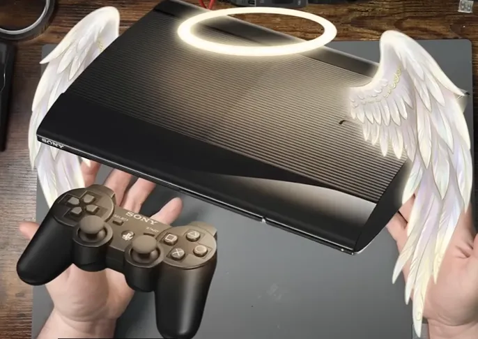
Chase wanted something the community had been chasing for years: persistent custom firmware features on Super Slim and late Slim models that never received official CFW support. Sony's later hardware revisions made traditional softmods unreliable or impossible. The goal was clear—boot a quasi-CFW (heavily based on Evilnat PEX) that keeps Cobra features alive, allows HDD key dumping, OtherOS, and system tools, while still giving a recovery path back to official firmware. That ambition only works if the hardware interface is rock-solid. One bad joint on the XDR CMD or CLK line and the console never leaves the black screen. Solid PCB-level decisions and careful manufacturing practices are what separate a working hack from a brick.
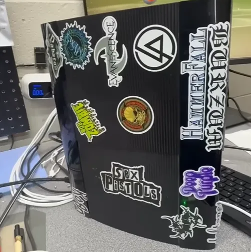
Watching the Triple-Beep Moment and Everything That Led There
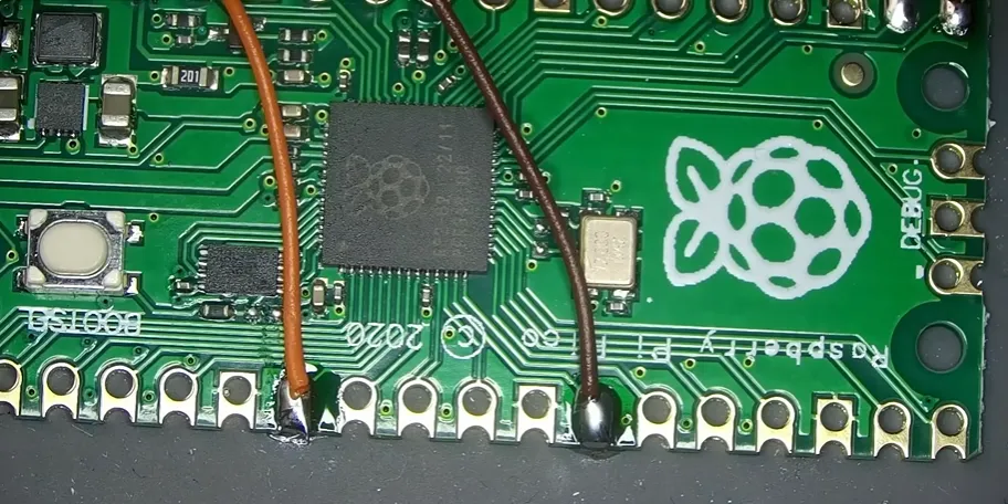
Chase starts the way any good repair tech should: verify the console, reinstall Hybrid Firmware, back up the NOR flash with Rebug Toolbox, then install the latest PS3HEN. Only after Stagex is written to flash does the hardware modchip go in. That order matters. The Pico is flashed with the BadWDSD .uf2, then four critical signal wires plus power and ground are run.
Watching the first successful boot is pure maker joy. The modchip LED flashes briefly, the console gives the classic triple beep, and "Bad WDSD detected" appears. After the qCFW install (10–20 minutes of a frozen-looking screen that is actually writing CoreOS), the Evilnat logo boots and the system is live. Chase even adds a small LED mod that re-purposes the standby light so the Pico status is visible without opening the case again. Those are the moments that make the late nights worth it—features that were supposed to be impossible on this hardware generation suddenly running on a $4 microcontroller board.
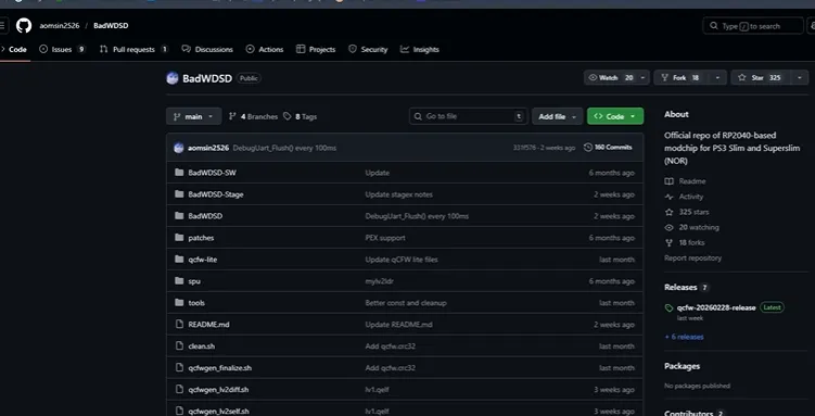
The clever engineering is in how little the modchip actually needs. Only CMD, CLK, SC_RX, and SC_TX are required for the core exploit. Everything else is optional. The RP2040 simply injects the stage entry code into XDR RAM at boot so the console loads Stagex from the NOR flash address. Once that path is open, the rest of the qCFW ecosystem (HDD key dump, OtherOS via petitboot, syscon access through the DEBUG pin at 576000 baud) becomes available.
Key Electrical Choices on the Pico and the Motherboard Pads
Even though the modchip starts life as a stock Raspberry Pi Pico (or RP2040-Zero), the success of the entire project lives or dies on the quality of the connections to the PS3 motherboard and the electrical characteristics of those short runs.
|
Parameter |
Recommendation / Observed Value |
Why It Matters |
|---|---|---|
|
Signal wire |
0.1 mm magnet wire |
Minimizes capacitance and inductance on high-speed XDR CMD/CLK |
|
Power / GND wire |
Thicker stranded or solid (not magnet) |
Low resistance under load; magnet wire can drop voltage |
|
CMD/CLK to GND resistance |
≈ 55 Ω |
Confirms the sense resistors and pads are intact |
|
Wire length |
As short as practical |
Reduces noise pickup and timing skew |
|
Flux |
High-quality no-clean (Stirri VS-UHF-TF) |
Clean joints without conductive residue |
|
Mounting |
Double-sided tape near disc-drive bay |
Avoids pressure from the shell and keeps wires tidy |
|
Optional pins |
HOLD, BANKSEL, DEBUG |
Recovery and diagnostics without full desoldering |
The Pico itself is a two-layer FR-4 board with the RP2040, onboard 3.3 V regulator, and USB for easy UF2 flashing. Chase's layout decisions were all about keeping the four signal wires short, routed away from noisy switch-mode areas, and strain-relieved so the shell closing pressure would not yank a joint.
Where the Build Almost Failed and How Chase Recovered
No honest build video is complete without the moments that make you wince. Chase left them in on purpose.
First came the classic TX/RX swap. The console would not talk to the modchip. After a careful re-solder the triple-beep returned. Next was physical space. The Super Slim is already packed; finding a spot for even a Pico that will not be crushed when the top shell is closed takes planning. Chase settled on the area near the disc drive and used tape and careful wire dressing.
The most critical and unforgiving part is the XDR interface itself. CMD and CLK are high-speed signals. Too-thick wire, excessive length, or a cold joint raises the chance of XDR RAM initialization failure. Early firmware versions simply left the console in a green light of death; later versions flash the modchip LED rapidly for five seconds and shut the console off. Measuring 55 Ω to ground on those pads before powering up is non-negotiable. One damaged resistor on the motherboard and recovery becomes a hardware-flasher job.
Chase also notes the wireless controller quirk: powering on with a Bluetooth pad forces an extra power cycle. A small software workaround exists, but it is another reminder that the modchip sits in a delicate timing path.
These are classic prototype-to-production lessons. Wire gauge, length, routing, and joint quality are DFM issues every bit as real as pad size or via aspect ratio on a custom board.
How AIVON Custom PCBs Turn Hand-Wired Experiments into Reliable, Shareable Hardware
What I love most about watching this project is how clearly it shows the difference between "it works on the bench once" and "it survives daily use and can be reproduced by others." Chase's careful choice of 0.1 mm magnet wire for the critical signals, thick conductors for power, short runs, thorough flux cleaning, and resistance verification are exactly the kinds of decisions we make every day on the factory floor.
A stock Pico plus flying wires is a brilliant proof-of-concept. The natural next step—and the step that turns a single successful repair into something the whole community can build with far higher success rates—is a purpose-designed custom PCB. That is precisely where AIVON's manufacturing capability becomes the quiet enabler.
Imagine replacing those four delicate magnet wires and the generic Pico outline with a single, compact AIVON-fabricated board. The CMD and CLK traces would be length-matched and impedance-controlled on a carefully chosen stack-up, eliminating the parasitic capacitance and inductance that cause XDR initialization failures. Power and ground would sit on solid planes instead of discrete wires, so voltage drop under the RP2040's load disappears. HOLD, BANKSEL and DEBUG pins would appear as clearly labeled test pads or small switches—no more guessing which wire is which. The board outline itself would be shaped to nest perfectly under the Super Slim's disc-drive bay, so shell pressure never becomes a mechanical risk again.
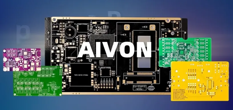
AIVON makes that transition practical. Upload the Gerbers and the free engineering review immediately flags the issues that matter for this kind of modchip: pad sizes that are marginal for hand soldering, via placement that would reduce yield, copper weight that is too light for reliable 3.3 V distribution, or solder-mask openings that leave too little copper for a solid joint. Material selection is straightforward—standard FR-4 with ENIG or immersion silver finish gives the clean, oxidation-resistant pads Chase needs when he is working under a microscope. If the design later moves to a tighter form factor or higher-speed signals, the same process supports controlled-impedance routing and even simple HDI features without forcing the creator into a different supplier.
Lead times measured in days, not weeks, mean a maker can order five or ten boards, test them in real Super Slims, tweak the silk-screen labels or add a tiny status LED footprint, and have the revised version in hand before the community loses interest. That rapid iteration loop is what elevates a one-off video success into a reliable, shareable hardware solution. The same DFM discipline that kept Chase's hand-wired version working is applied systematically: consistent plating thickness, clean registration, and electrical testing so every board that leaves the factory behaves the same way.
In short, the Pico got the first console across the finish line. An AIVON custom PCB is what lets the next hundred builders start with a board that already incorporates the signal-integrity lessons, the recovery features, and the mechanical fit that Chase had to discover the hard way. That is how an ambitious idea becomes something the whole scene can trust.
DFM Checklist for RP2040-Based Console Modchips
|
Check Item |
Target / Guideline |
Why It Matters for This Project |
|---|---|---|
|
CMD/CLK wire gauge |
0.1 mm magnet wire |
Preserves XDR timing margins |
|
Power/GND conductors |
Thicker than signal wires |
Prevents voltage drop under Pico load |
|
Wire length & routing |
Shortest practical, away from SMPS & clocks |
Reduces noise and skew |
|
Pre-power resistance check |
≈ 55 Ω CMD/CLK to GND |
Catches damaged sense resistors early |
|
Flux residue |
Thorough IPA clean after soldering |
Avoids leakage on high-impedance pads |
|
Mechanical strain relief |
Tape or adhesive near every joint |
Shell pressure will not lift pads |
|
Recovery path |
HOLD and BANKSEL accessible |
Soft recovery without full desolder |
|
LED / status visibility |
External or re-purposed existing LED |
User can confirm modchip state without opening |
Why This Kind of Transparent Build Still Matters
Chase Fournier's video is more than a cool hack. It is a transparent, entertaining masterclass in treating a high-stakes console mod with the respect it deserves. He showed the mistakes, the fixes, the joy of the triple beep, and the final Evilnat logo. The result is a Super Slim that can do things Sony never intended, recovered through careful work rather than magic.
If you are a maker staring at a pile of modules and wires and wondering how to make the next version cleaner, more repeatable, and ready for real use, the path is clear. Design the board, run the DFM checks, and get it manufactured properly. The tools and the partners exist. The only remaining question is what you will unlock next.
FAQ
Q1: Why is 0.1 mm magnet wire specifically recommended for CMD and CLK?
A1: Those lines carry high-speed XDR interface signals. Thicker wire adds capacitance and inductance that can push the timing outside the window the RP2040 expects. Magnet wire keeps the electrical length short and the parasitic loading minimal.
Q2: What happens if the CMD/CLK resistance to ground is not around 55 Ω?
A2: It usually means a damaged resistor or cracked pad on the motherboard. Powering up in that condition risks XDR initialization failure and can leave the console unable to boot even with the modchip removed. Measure before you apply power.
Q3: Can I design a custom PCB instead of using a stock Pico?
A3: Absolutely. A custom board lets you length-match the critical traces, put power planes under the RP2040, label every pad, and shape the outline to the exact cavity inside the Super Slim. That is precisely the kind of small, signal-sensitive design that benefits from professional DFM review and controlled-impedance manufacturing.
Q4: Is eMMC-based 4x00 supported?
A4: No. The current exploit relies on a specific NOR flash layout for Stagex. eMMC models lack the equivalent address window, so the hardware modchip cannot redirect boot the same way.
Q5: What surface finish and copper weight would you recommend for a production modchip PCB?
A5: ENIG or immersion silver for reliable hand-soldered joints on fine pads, and 1 oz copper minimum so the power distribution stays solid even on a small board. Those choices keep assembly yield high when builders are working with the same tools Chase used.
Q6: How do I recover if the console will not boot after a bad flash?
A6: First try the HOLD pin to disable the modchip. If that fails, short BANKSEL to ground, power the console so the modchip forces OFW mode, then enter safe mode and reinstall official firmware. Always keep a NOR backup.