










SMD Parts Removal with Soldering Iron: Reliable Techniques Without Hot Air
What This Video Coevrs
This video demonstrates practical techniques for PCB component removal when hot air tools are unavailable. It focuses on safely desoldering surface-mount devices (SMD) using only a standard soldering iron, flux, and basic tools like tweezers or a solder sucker.
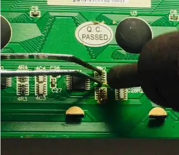
The method involves applying plenty of flux to all pins, then heating each pad evenly in a methodical side-to-side pattern while gently lifting the component. Patience and controlled heat are critical to prevent lifted pads, damaged traces, or board delamination. A successful removal leaves clean, bright pads ready for new component placement.
These skills help reduce scrap rates and rework costs during troubleshooting, repairs, or engineering changes. Proper techniques support reliable outcomes in PCB prototype development and PCB assembly workflows.
Engineers working on dense or high-reliability designs will find this especially useful for applications such as consumer electronics PCB, industrial control PCB, and medical devices PCB, where quick and safe component replacement can save significant time and expense.
Key Highlights
- Apply generous flux and use a fine-tip soldering iron to heat pads evenly while gently lifting SMD components with tweezers.
- Work methodically from one side to the other with controlled heat to avoid damaging pads or traces on the PCB.
- Successful iron-only removal leaves clean, undamaged pads ready for reliable reinstallation of new components.
Step-by-Step Soldering Iron Desoldering Process
Effective SMD parts removal with a soldering iron requires a systematic approach grounded in thermal management principles. Begin by securing the PCB on a stable work surface and thoroughly cleaning the area around the target component to remove contaminants that could impede heat transfer or cause solder bridging.
Apply a liberal amount of high-quality, no-clean flux across all pins or pads of the SMD component. Flux reduces surface tension, improves heat distribution, and protects pads during the process. Select a fine-tip or chisel-tip soldering iron set to an appropriate temperature, typically 320–380°C depending on the board material and component size, to ensure rapid solder reflow without prolonged heat exposure.
Heat pads sequentially in a side-to-side or corner-to-corner pattern, allowing the solder to fully melt before applying minimal lifting force with tweezers. For multi-pin components like SOIC or QFN packages, alternate sides to maintain even thermal distribution and minimize stress on individual pads. Once all joints are molten, lift the component cleanly. Follow up by cleaning residual solder from pads using desoldering braid or a solder sucker for a flat, oxide-free surface.
Common Manufacturing Challenges and Failure Modes
In production and repair environments, SMD desoldering with only a soldering iron presents specific risks that can lead to costly board failures. Excessive localized heat often causes pad lifting, especially on thin or flexible PCBs common in consumer electronics. Rapid temperature changes can also induce trace cracking or delamination, particularly in multilayer boards used in industrial control systems.
Another frequent issue is incomplete solder reflow on one side of the component, leading to uneven lifting forces that tear copper pads or create micro-fractures invisible during initial inspection but problematic in field operation. Over-application of force before full melt exacerbates these problems, while insufficient flux results in poor wetting and cold joints during reinstallation.
Real-world data from rework stations shows that proper technique reduces pad damage rates by over 70% compared to rushed methods. Mitigation involves strict temperature control, preheating the board if possible, and inspecting pads under magnification post-removal to verify integrity before proceeding with new component placement.
DFM Best Practices for Improved Component Removal
Design for Manufacturability (DFM) principles play a critical role in facilitating future rework of SMD components. Incorporate adequate pad extensions and thermal relief connections where possible to improve heat sinking and reduce the risk of pad detachment during desoldering. Component orientation and spacing should allow clear access for soldering iron tips without interfering with adjacent parts.
Specifying board materials with higher Tg ratings enhances thermal resilience during repeated rework cycles. For high-density designs, consider adding test points or fiducials near critical components to support precise alignment during repair operations.
In prototype and low-volume production, these DFM considerations enable technicians to perform SMD parts removal with soldering iron efficiently, supporting faster iteration cycles and lower overall project costs. Manufacturers should review layouts against established IPC standards for reworkability to balance functionality with serviceability.
Recommended Parameters
| Parameter | Recommended Range | Impact on Rework Success |
|---|---|---|
| Soldering Iron Temperature | 320–380°C | Ensures quick reflow while minimizing thermal stress on PCB |
| Flux Type | No-clean or RMA | Improves solder flow and protects pads from oxidation |
| Tip Size | Fine chisel or conical (0.5–1.0 mm) | Provides precise heat control on small SMD pads |
| Dwell Time per Pad | 2–4 seconds max | Prevents overheating and pad lift |
Tools and Materials for Successful SMD Rework
Proper tool selection significantly influences outcomes in iron-only SMD removal. A temperature-controlled soldering station with interchangeable tips allows precise adjustment for different component sizes and board thicknesses. High-quality liquid or gel flux, desoldering wick, and precision tweezers are essential for clean execution.
Additional supportive tools include a solder sucker for through-hole cleanup and magnification tools or microscopes for post-removal inspection. In manufacturing settings, maintaining calibrated equipment and documented procedures ensures repeatability across technicians and shifts.
FAQ
Q1: How do you remove SMD components without hot air?
A1: Apply plenty of flux, use a fine-tip soldering iron to heat each pad evenly, and gently lift the component with tweezers or a solder sucker while working side to side.
Q2: What is the biggest risk when removing SMD parts with a soldering iron?
A2: The main risk is lifting pads or damaging traces due to excessive heat on one area or applying force before the solder is fully melted.
Q3: When is the soldering iron method preferred for PCB rework?
A3: The soldering iron method is ideal for simple SMD removal, small components, or when hot air stations are not available during prototype debugging or field repairs.
Q4: How can DFM principles reduce risks during future SMD desoldering?
A4: Incorporating larger pad areas, thermal reliefs, and sufficient component spacing allows better heat distribution and mechanical strength, making soldering iron removal safer and more reliable in production and repair scenarios.
Q5: What temperature should be used for SMD parts removal with a soldering iron?
A5: Maintain 320–380°C depending on board thickness and component mass. Always prioritize the lowest effective temperature and shortest dwell time to protect sensitive laminates and traces in high-reliability applications such as medical devices PCB.
No hot air? No problem. You can successfully remove SMD parts using just a soldering iron with the right technique.
In this video, I'll show you how to desolder surface-mount components cleanly without hot air. Apply plenty of flux to all pins, then use a fine-tip iron to heat each pad evenly while gently lifting with tweezers or a solder sucker. Work methodically from one side to the other.
The key is patience and controlled heat to avoid damaging pads or traces. This is what a clean removal looks like — bright, undamaged pads ready for new components and better rework.
Try this method and upgrade your soldering skills!





