


Engineering Cases
Engineering Cases focuses on real PCB engineering reviews, manufacturing challenges, and production optimization processes from actual fabrication projects. This category highlights how different PCB designs are evaluated and adjusted during engineering review, covering topics such as stack-up analysis, impedance control, drill optimization, copper balancing, solder mask alignment, DFM review, and production risk assessment across various PCB applications. The content in this section is based on practical manufacturing scenarios rather than theoretical introductions. Each engineering case demonstrates how specific PCB issues are identified, analyzed, and resolved during production preparation and fabrication. These records help engineers, purchasers, and hardware teams better understand the relationship between PCB design decisions and manufacturing stability, yield control, and process reliability. Topics may include multilayer PCB engineering review, HDI process optimization, flexible PCB manufacturing considerations, heavy copper processing adjustments, surface finish selection, Gerber data verification, and other real-world PCB production experiences. By organizing engineering challenges and process solutions into structured case content, this category provides valuable insight into practical PCB manufacturing and engineering workflow management.
Featured Blog
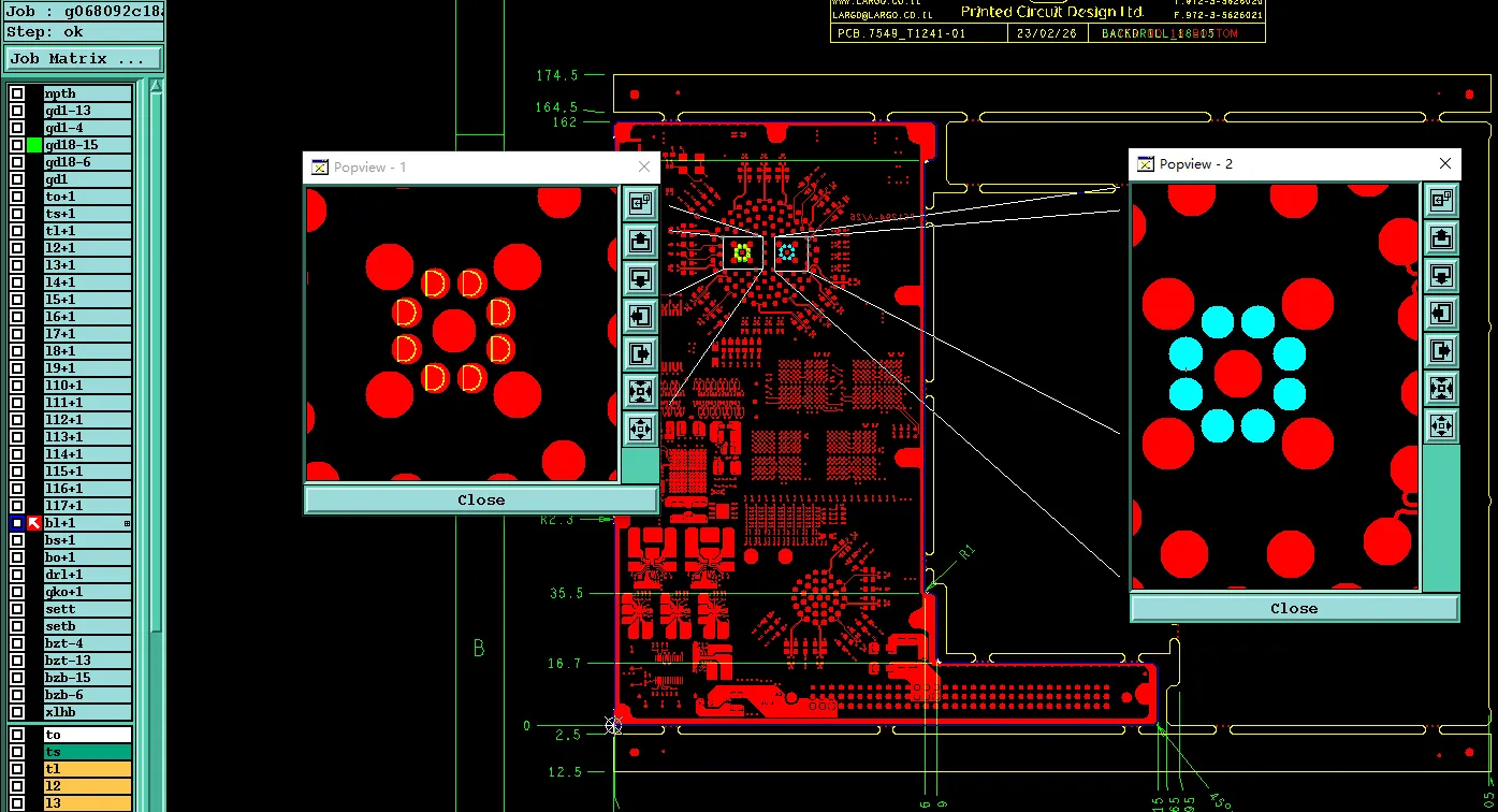
PCB Hole Attributes and Special Drilling: Common CAM Review Conflicts
See how CAM reads PCB hole attributes and special drilling—PTH vs NPTH, back drill, press-fit holes, countersink, and laser vias—and why incomplete data delays fabrication.
Latest Blogs
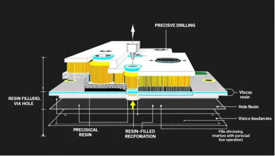
Which Vias Need Resin Plugging? Real Engineer Questions from Production
Confirm resin plugged vias in CAM: vias overlapping SMT pads, guard vias on the same drill tool, solder mask openings on holes called out for fill, and a VIA Plug layer against an order cover-oil note.
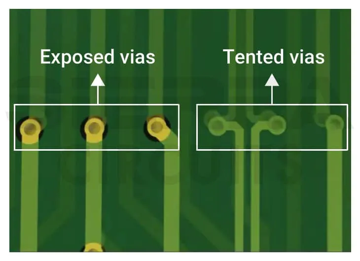
Via Tenting vs Opening: When Order Notes Conflict with Gerber Solder Mask Data
When an order note says tent, cover oil, or plug but Gerber shows solder mask openings on the same vias, CAM cannot guess. This article explains via tenting vs opening, mixed boards, and EQ close paths.
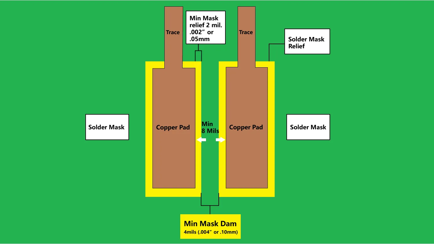
Why Your Solder Mask Bridge Keeps Failing – Real Spacing Limits from Production
Learn why PCB solder mask bridges fail when pad spacing leaves too little mask web, how CAM reviews SMD, IC and BGA geometry, and when open windows or gang openings require confirmation.
PCB Hole Attributes and Special Drilling: Common CAM Review Conflicts
See how CAM reads PCB hole attributes and special drilling—PTH vs NPTH, back drill, press-fit holes, countersink, and laser vias—and why incomplete data delays fabrication.
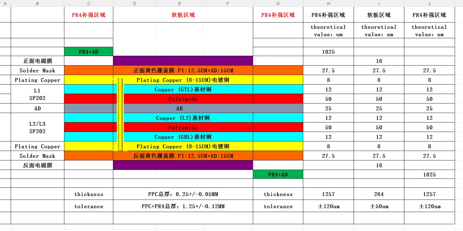
PCB Stackup, Impedance and Thickness Issues in CAM Review
When PCB stackup, impedance, and board thickness notes disagree, CAM cannot book one press-up. See stock, Z-trace, copper-weight, and thickness conflicts—and what to lock before build.
Real Panelization, V-Cut and Edge Clearance Issues from Production
See why CAM review holds jobs when PCB panelization and outline are undefined: process edge, V-cut clearance, stamp holes, and edge copper exposure. Confirm them before fab.
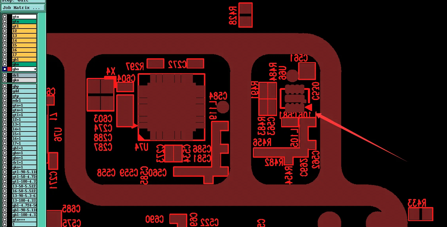
PCB Silkscreen and Marking: Common CAM Issues and Manufacturing Considerations
Understand PCB silkscreen and marking issues found in CAM review, including silkscreen on pad, small text, UL mark placement, date code PCB, and factory logo silkscreen, plus manufacturing considerations before release.
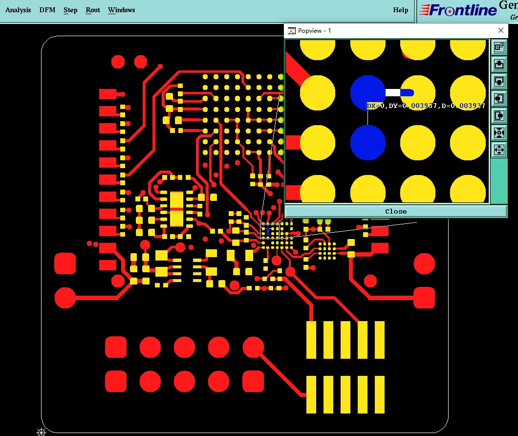
PCB Solder Mask and Via Design Issues: What CAM Review Commonly Finds
Learn real PCB solder mask and via design issues found in CAM review, including solder mask bridge failures, via tenting vs open conflicts, resin plugged vias problems, and layer mismatches, plus practical ways to prevent them.
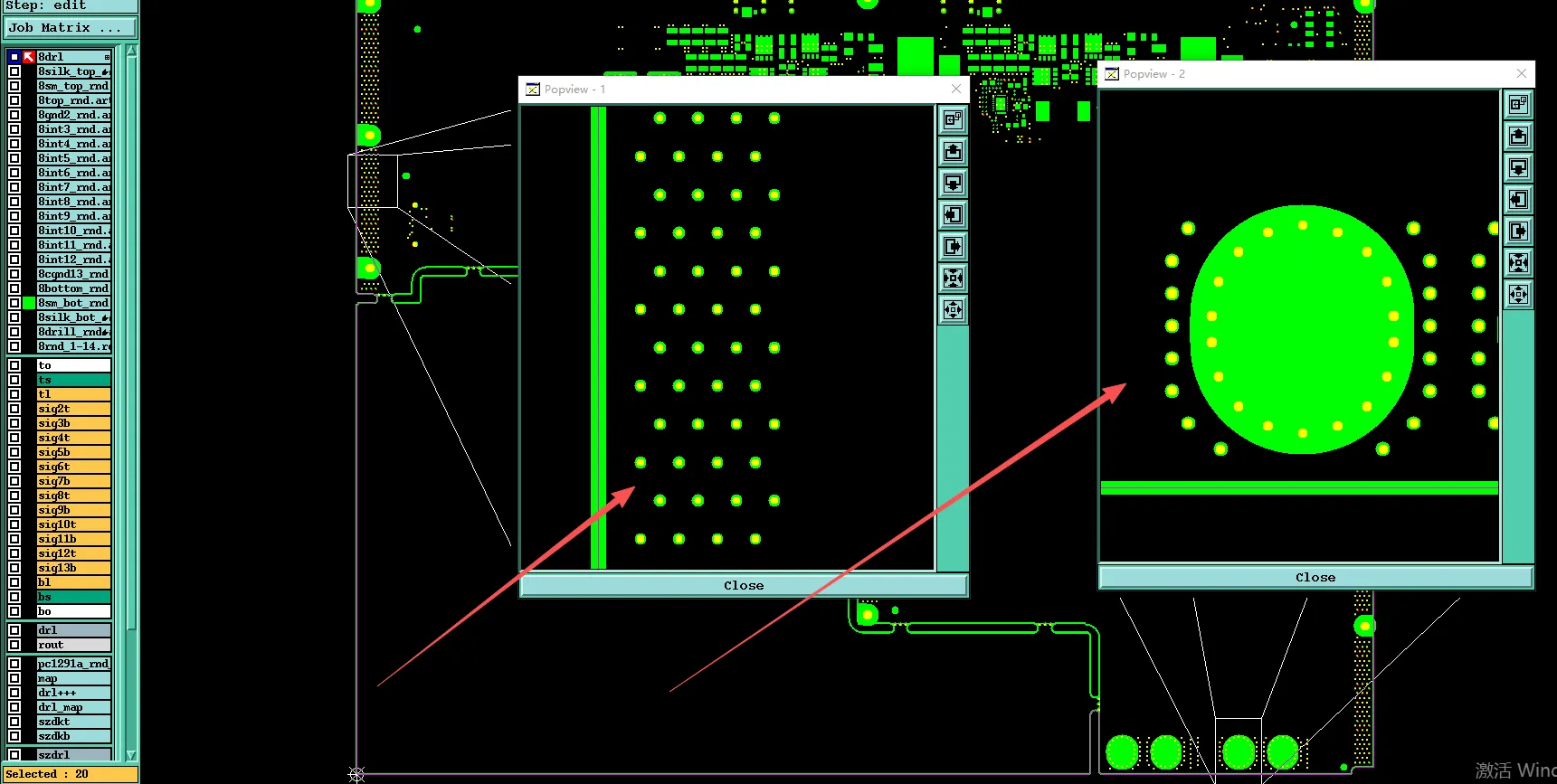
How We Resolved Resin Plug Tenting Conflict on 14-Layer PCB
CAM review of a 14-layer board found resin-plug and tenting notes conflicting with bottom-layer mask openings. All vias including guard holes were confirmed for plugging and tenting before production release.
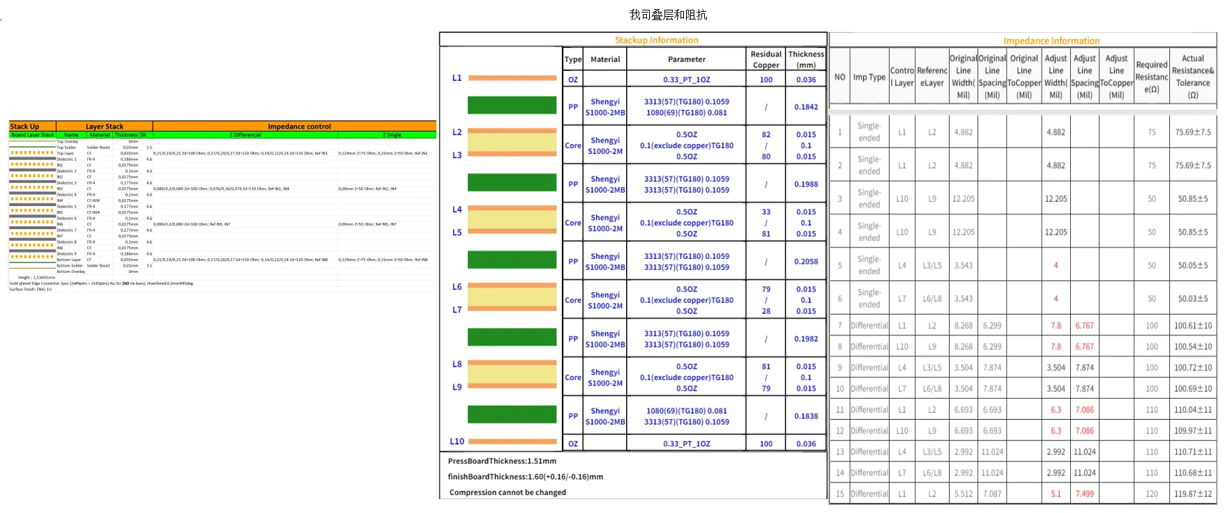
How We Fixed Impedance Line Conflicts on 10-Layer PCB
CAM review of a 10-layer impedance-controlled board found differential spacing mismatches and traces on non-existent layers. Stackup was adjusted for available materials and line geometry corrected to meet targets before production.
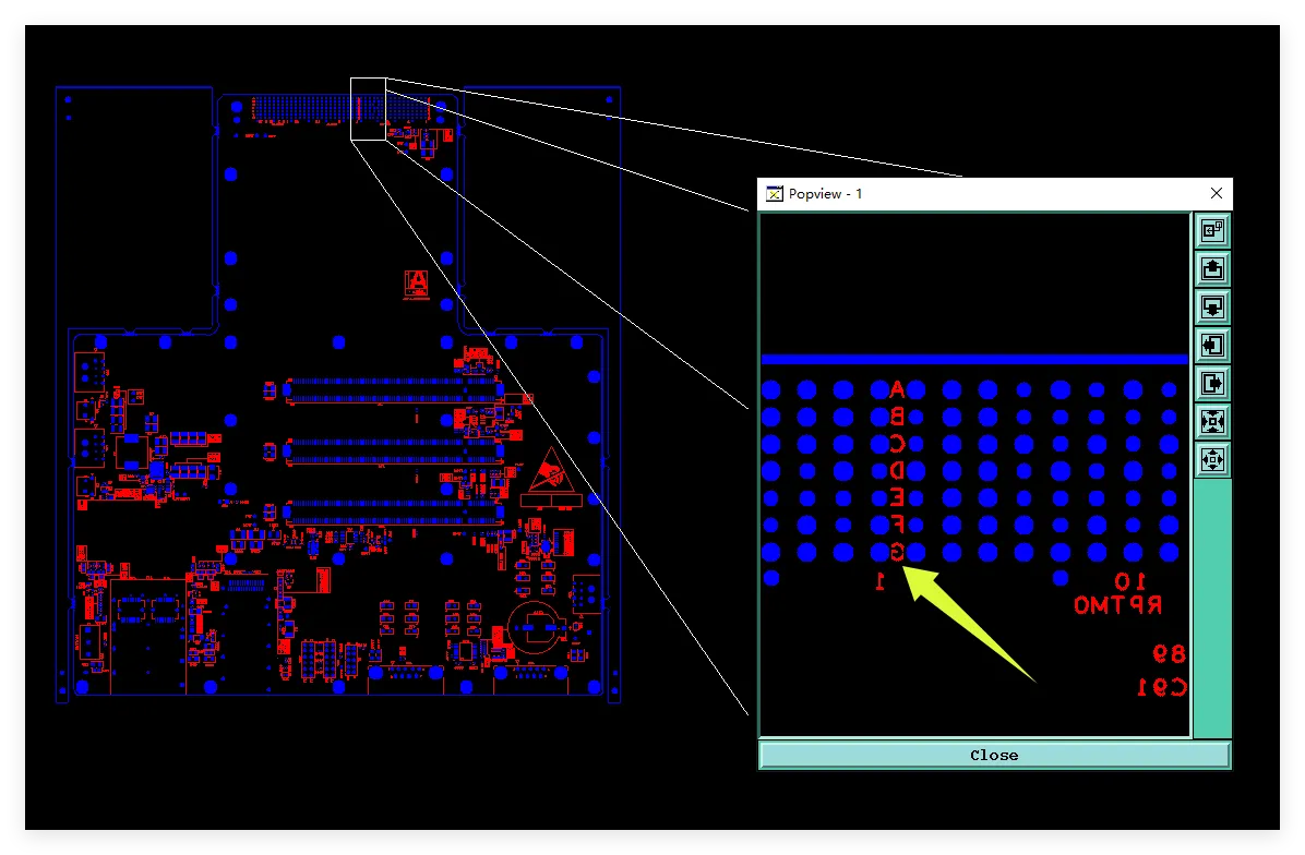
How DFM Prevented Back Drill Dimples in 12-Layer PCB
Learn how DFM review resolved back drill dimples, PTH/NPTH hole mismatches, and missing impedance traces on a 12-layer FR4 PCB, preventing assembly defects, open circuits, and signal integrity risks before production.
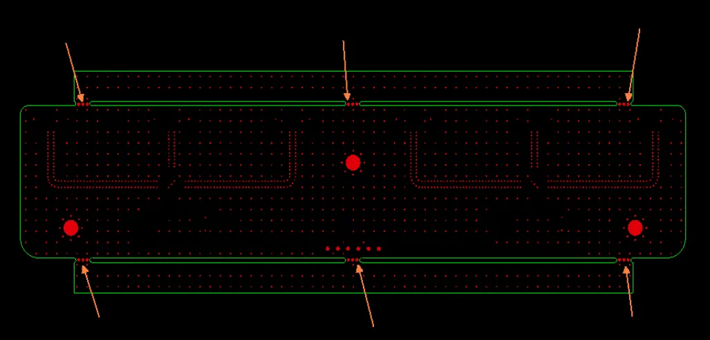
Why 0.267 mm Stamp-Hole Spacing Failed on Rogers RO4350B PTH Boards
Original 0.267mm stamp hole spacing on Rogers RO4350B with PTH holes risked board breakage. See how reducing diameter to 0.5mm and spacing to 0.4mm restored process capability for reliable depanel


