PCB Panelization Issues: Avoid EQ Delays on Rails & Depanel
Key Moment
What This Video Covers
This video examines four recurring panelization issues drawn from actual PCB fabrication orders. Even when the circuit design itself is clean, manufacturers frequently pause production to confirm how multiple boards should be arrayed, how process edges (manufacturing rails) should be structured, how boards will be separated after assembly, and which auxiliary features—tooling holes, fiducial marks, and rail copper—must be present for handling and registration.
PCB panelization is not merely an efficiency step; it determines whether a panel can be clamped, aligned, processed through SMT or through-hole lines, and cleanly depanelized without damaging finished boards. Inconsistent data between Gerbers and fabrication drawings, insufficient rail width for machine clamps, mismatched separation methods (V-scoring versus breakaway tabs with stamp holes), and missing registration features are common sources of engineering queries (EQs).
These details matter for both low-volume PCB prototype runs and higher-volume PCB mass production. On standard FR4 PCB panels they directly affect yield, handling risk, and whether the boards can move smoothly into PCB assembly. Clarifying them before files leave engineering reduces back-and-forth and keeps schedules intact.
Key Highlights
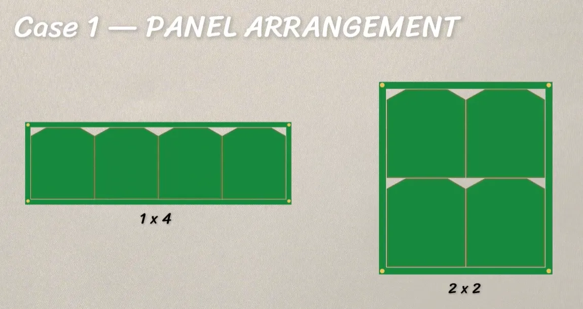
- Conflicting panel layouts (for example 1×4 versus 2×2) in different production files force the factory to stop and confirm the final array before release.
- Manufacturing rails must provide enough width, corner treatment, and clearance for clamps and positioning tools; treating them as pure scrap material is a frequent source of process holds.
- Separation method (V-scoring on straight edges versus stamp-hole breakaway tabs on irregular outlines or near-edge components) must be chosen at panel design time, because it affects both panel strength during fabrication and clean depanelization after assembly.
Case 1: Resolving Conflicting Panel Arrangement Data
A common EQ occurs when one document shows a 1×4 strip while another shows a 2×2 matrix. Both arrangements can be manufacturable, yet the factory cannot proceed until a single, authoritative layout is confirmed. Differences in unit count, rotation, or overall panel size also change rail length, scrap area, and the positions available for fiducials and tooling holes.
In practice, CAM engineers overlay the outline layer, panel drawing, and any fabrication notes. When the overlays disagree, the job is placed on hold. The resolution is straightforward: freeze one panel definition in the package—preferably on a dedicated panel drawing that shows board count, orientation, rail placement, and separation features—and ensure every other file references the same definition. Leaving the arrangement as "factory to advise" simply transfers the decision into an EQ cycle.
For rectangular boards that fit standard process panels, designers often maximize utilization by testing both linear and grid arrangements. The final choice should also consider how the panel will travel on the assembler conveyor and whether any edge must remain free of rails for cosmetic or impedance reasons.
Case 2: Designing Manufacturing Rails That Survive the Line
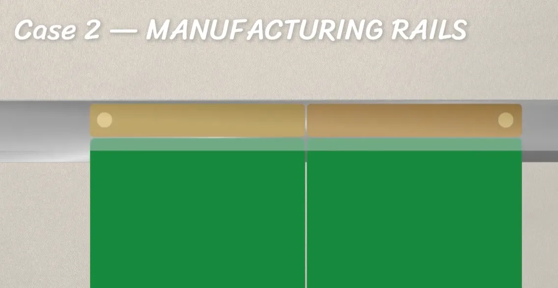
A panel may already contain the correct number of boards yet still require confirmation of the edge rails. Rails (also called process edges or break-off borders) exist so automated equipment never has to clamp a finished product edge. They also provide space for global fiducials and tooling holes.
Typical production feedback shows that rails narrower than approximately 8 mm frequently fail to clear edge clamps or worn conveyor belts, especially on 1.6 mm FR4. Rails drawn as sharp rectangles may also need chamfer or radius treatment for packing and handling. Copper poured across a narrow rail can become a peel strip during later scoring or tab break; a copper-free contact zone along the outer edge is usually preferred unless the process specifically needs rail copper for resin-flow or plating balance.
Two parallel rails keep the panel flatter through reflow than a single-sided rail. Once rail width, corner style, and copper intent are defined on the panel drawing, the factory can match the array to its fixtures without further clarification.
| Rail Parameter | Typical Production Consideration | Risk if Undefined or Undersized |
|---|---|---|
| Width | 8–10 mm commonly clears clamps and leaves room for a 1 mm fiducial plus keep-out | Clamp contact on finished edge or insufficient space for registration features |
| Corner treatment | Chamfer or radius preferred for handling | Sharp corners snag or complicate packing |
| Copper on rail | Optional for balance; copper-free outer zone preferred for clamping | Peel or scrap contamination if continuous copper meets the clamp zone |
| Placement | Two parallel long-side rails preferred | Single-sided rails increase twist risk |
Case 3: Choosing the Right Board Separation Method
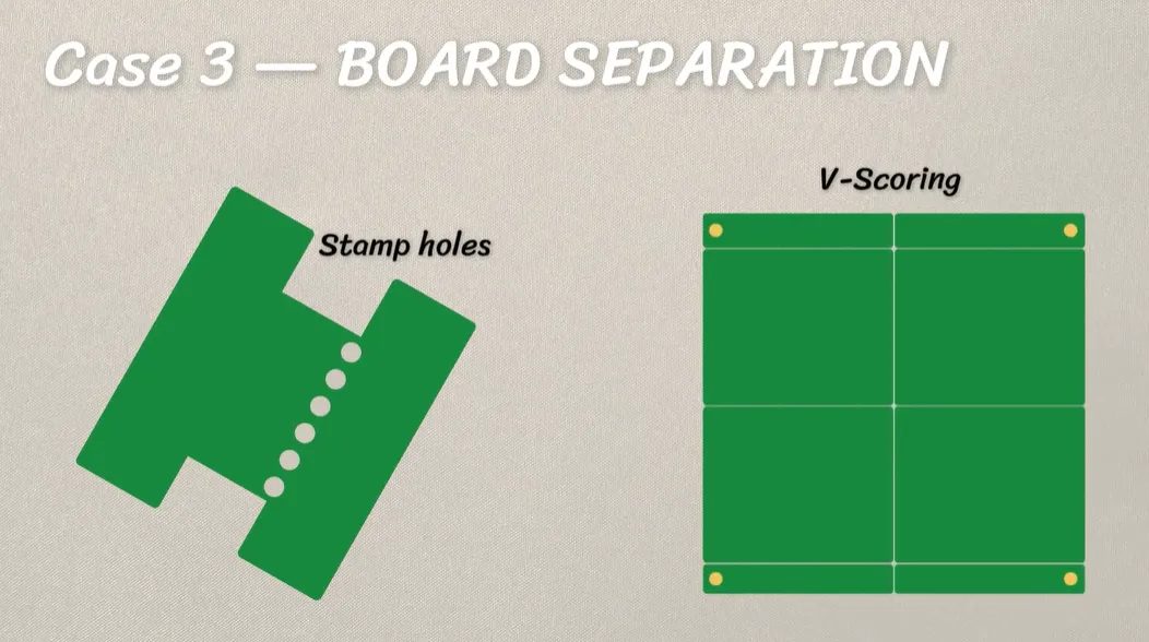
After assembly the individual boards must still be separated. For straight, rectangular outlines with adequate edge clearance, V-scoring (V-cut) is efficient: a residual web, typically about one-third of board thickness, remains and is snapped later. V-scoring requires a continuous straight path that runs the full length of the panel and sufficient copper keep-out so that planes and traces do not crack when the web is broken.
Irregular outlines, or components placed close to the edge, usually require routed breakaway tabs with stamp holes (mouse bites). Stamp holes weaken the tab so the board can be snapped cleanly while the panel remains rigid enough for fabrication and assembly. Hole diameter, pitch, and remaining bridge width control both process strength and break force; undersized tabs can fracture during drilling, plating, or handling, while oversized tabs can crack the board or nearby joints at depanelization.
Mixing V-cut and stamp holes on the same connecting web reduces residual strength further and is frequently flagged unless the designer explicitly accepts the weaker connection. The separation method should therefore be selected and documented when the panel is designed—not after the boards are finished.
| Separation Method | Best Application | Key Design Constraint | Main Risk |
|---|---|---|---|
| V-scoring | Straight rectangular edges, adequate clearance | Continuous score line; copper keep-out from score centerline | Cracked copper or components if clearance is insufficient |
| Stamp-hole tabs | Irregular outlines or near-edge components | Hole size, pitch, and bridge alignment on the tab | In-process breakage if tabs are too weak; rough edge or cracked boards if too strong |
| Mixed | Intentional hybrid arrays | Explicit note that reduced web strength is accepted | Unplanned panel fracture in transit or processing |
Case 4: Defining Tooling Holes, Fiducials, and Rail Copper
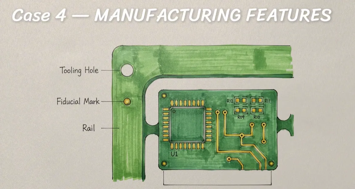
Even when the circuit data is complete, the panel itself may still lack the features required for mechanical alignment and machine vision. Tooling holes allow pins to locate the panel; fiducial marks give cameras a reliable coordinate origin; and certain processes call for copper on the rails for plating or resin-flow balance.
These features are easy to overlook because they do not belong to the finished board. When they are missing, CAM typically proposes a standard set on the process edge (for example, non-plated tooling holes of common diameters such as 2.0 mm or 3.0 mm together with 1 mm copper fiducials) and requests confirmation. Specifying plated versus non-plated tooling holes, fiducial diameter, mask opening, and keep-out, and stating whether rail copper is required, eliminates the query.
Fiducials must remain free of solder mask, silkscreen, and nearby vias so the vision system can lock reliably. Placing them on the rails keeps them off the product while still available during assembly. Once the rails are broken away, any features that must remain on the finished board have to be designed as product features rather than panel tooling.
Common Panelization Failure Modes and How to Prevent Them
In production, the same clusters of problems reappear. File sets that contain two different panel definitions create an immediate hold until one is chosen. Rails that are too narrow or that carry continuous copper into the clamp zone cause handling defects or force a redesign. Separation methods that cross copper or that combine V-cut and stamp holes without an explicit strength note lead to cracked boards or in-process breakage. Missing or poorly placed fiducials and tooling holes stop automated lines even when the circuit itself is correct.
The practical remedy is to treat the panel as a temporary mechanical workpiece whose registration, clamping, and separation features must be defined before files are released. A single panel drawing that shows array count and orientation, rail geometry and copper intent, separation method and keep-outs, and the locations of tooling holes and fiducials removes the majority of these EQs. When the designer cannot yet decide every detail, clear limits (for example, "ship as single," "no rail on named edge," "V-cut only") still give CAM a usable boundary instead of an open-ended request.
FAQ
Q1: Why does the factory ask me to confirm panel arrangement when both layouts look valid?
A1: Different files can show different unit counts, rotations, or overall panel sizes. Because rail length, scrap area, and the available space for fiducials and tooling holes all change with the array, production cannot start until one authoritative layout is locked.
Q2: How wide should manufacturing rails be for standard FR4 panels?
A2: Rails of 8–10 mm commonly clear edge clamps, leave room for a 1 mm fiducial plus keep-out, and still break cleanly. Narrower rails frequently fail on certain conveyor or clamp systems and trigger confirmation requests.
Q3: When should I use V-scoring versus stamp-hole tabs?
A3: Use V-scoring for straight rectangular edges with adequate copper keep-out. Use stamp-hole breakaway tabs for irregular outlines or when components sit close to the edge. Mixing both methods on the same web reduces strength and usually requires explicit acceptance.
Q4: Do tooling holes and fiducials need to be on the finished board?
A4: Usually they belong on the process rails so they do not consume product area and so they remain available during assembly. Features that must survive depanelization should be designed as part of the board itself rather than as panel tooling.
Q5: What happens if rail copper requirements are not stated?
A5: CAM may add or remove rail copper depending on plating or resin-flow needs, or it may hold the job for confirmation. Stating whether copper is required, optional, or prohibited on the rails removes the ambiguity.
Your PCB design is ready for production. But then the factory asks: "How should this panel be built?"
The board itself may be fine. The question is how it should be arranged and prepared for the production line.
Based on real PCB orders, we've gathered four common panelization issues to help you avoid potential delays and get your boards into production more smoothly.
CASE 01: PANEL ARRANGEMENT
First, panel arrangement.
Here's a simple case: the fab drawing shows a 1×4(one-by-four) panel, but another production note shows a 2×2 layout.
Both can work. But which one should the factory build?
When different files show different panel layouts, the factory needs to confirm the final one before production.
So the key is simple: make sure the panel arrangement is consistent across your production files.
CASE 02: MANUFACTURING RAILS
Next, manufacturing rails.
A panel may already be arranged, but the factory may still need to confirm the edge rails.
For example, the rail may not leave enough space for machine clamps or positioning tools. Its width or corner shape may also need to be adjusted for the production line.
So don't treat the rail as just extra material around the PCB.
Check that the rail structure matches the equipment and process being used.
CASE 03: BOARD SEPARATION
Third, board separation.
Once the boards are assembled, they still need to come apart.
For a straight board edge, V-Scoring may work. But with an irregular outline—or components close to the edge—you may need breakaway tabs with stamp holes instead.
So the way the boards are connected affects how they can be separated later.
That's why the separation method should be decided when the panel is designed, not after it's finished.
CASE 04: MANUFACTURING FEATURES
Fourth, manufacturing features.
The PCB itself may be ready, but the panel may still need a few things for production.
For example, tooling holes can help with mechanical alignment, fiducial marks help machines locate the panel, and some processes may require copper on the rails.
These details are easy to overlook because they aren't part of the PCB itself.
So if they're needed for your production process, define them when you build the panel—not later.
Before submitting your panelized PCB, run through this quick checklist to keep your project moving smoothly.
✓ Panelization method is clearly defined
✓ Manufacturing rails are included
✓ Board connections are specified
✓ Tooling holes and fiducials are considered
✓ Any rail copper requirements are clearly indicated
Clarifying these panelization details early helps avoid unnecessary engineering queries before production begins.
Have a PCB project ready? Check out AIVON through the link in our profile.And don't forget to claim your new-customer offer for your first order.