










Safe QFP Chip Removal from PCB with Hot Air Rework
What This Video Covers
This video demonstrates professional techniques for safely removing QFP (Quad Flat Package) chips from a PCB during rework. QFP removal requires precise control to prevent lifted pads, damaged traces, or board delamination.
Key steps include positioning the hot air nozzle approximately one centimeter above the component, setting temperatures between 320–380°C, and moving the airflow evenly around all four sides in small circular motions for uniform heating. Once the solder fully reflows, gently lift the chip with tweezers — never force it. If the component does not release easily, continue heating to avoid damage.
These methods ensure clean removal with intact pads ready for new components. Proper QFP rework techniques are essential during PCB prototype troubleshooting, field repairs, and PCB assembly modifications.
The guidance supports high-reliability applications such as medical devices PCB, automotive PCB, and industrial control PCB, where precise component replacement helps maintain signal integrity and overall board reliability.
Key Highlights
- Position hot air nozzle ~1cm above the QFP and use 320–380°C while moving evenly around all sides for uniform heating.
- Wait for complete solder reflow before gently lifting with tweezers — never force the component.
- Controlled circular motion and patience prevent pad lifting and trace damage during QFP removal.
Essential Nozzle Positioning and Temperature Control for QFP Packages
Successful QFP chip removal depends on maintaining a consistent thermal profile that melts solder joints without overheating the substrate or the component body. Holding the hot air nozzle approximately one centimeter above the package allows the air stream to expand and distribute heat across all four rows of leads simultaneously. Closer distances concentrate heat on the package top, raising the risk of internal die damage or excessive board surface temperature.
Temperature selection within the 320–380°C range accounts for typical lead-frame thermal mass and the melting point of common lead-free solders. Lower settings may leave residual solid solder that resists removal, while higher settings accelerate oxidation and can initiate copper pad lifting or resin degradation in FR-4 laminates. Operators monitor the solder fillet appearance under magnification; a shiny, fully liquid meniscus around every lead indicates readiness for extraction.
In production rework environments, boards with thick copper planes or large ground pours require slightly longer dwell times or a mild board preheat to equalize thermal gradients. Skipping preheat often forces operators to raise nozzle temperature, increasing the probability of localized delamination. Consistent application of these parameters yields repeatable results across QFP body sizes from 7 × 7 mm to larger 28 × 28 mm packages.
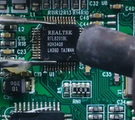
Uniform Heating Patterns That Protect Pads and Traces
Even heat distribution is achieved by continuous small circular or figure-eight motions that travel along all four sides of the QFP. Stationary dwell over any single side creates differential expansion between the plastic body and the copper leads, which can shear solder joints or lift pads on the opposite side once force is applied.
The circular motion also prevents shadowing effects caused by the package body itself. Leads on the far side of the airflow path receive adequate energy only when the nozzle path systematically covers the full perimeter. Experienced technicians complete two to three full circuits after the first visual indication of solder melt to ensure every joint reaches liquidus.
Failure to maintain motion frequently results in incomplete reflow on corner leads, the locations most prone to pad lift because of higher mechanical stress during extraction. Documented process controls in high-reliability manufacturing therefore specify both temperature and motion pattern as critical process parameters for QFP rework.
Common Failure Modes During QFP Hot Air Removal and Prevention Methods
The most frequent defect observed in QFP removal is pad lifting, caused by residual solid solder combined with upward force from tweezers. Once a pad separates from the laminate, repair requires either micro-soldering a copper bridge or scrapping the board. Prevention centers on confirming full reflow through visual inspection of all four sides before any lifting force is applied.
A second common failure is trace cracking or necking near the pad entry. This occurs when heat is applied unevenly and the operator twists the component during extraction. Maintaining pure vertical lift after complete melt eliminates shear stress on the traces.
Board delamination appears as white or cloudy areas in the laminate when surface temperature exceeds the glass-transition threshold for prolonged periods. Limiting nozzle temperature to the upper end of the recommended range and using intermittent rather than continuous heating cycles reduces this risk. In multilayer boards carrying high-speed signals, any of these defects can introduce impedance discontinuities that only become apparent during later functional testing.
| Parameter | Recommended Setting | Primary Risk if Outside Range | Mitigation Practice |
|---|---|---|---|
| Nozzle distance | ~1 cm above package | Localized overheating or insufficient melt | Verify clearance with gauge or visual check |
| Air temperature | 320–380 °C | Incomplete reflow or laminate damage | Start mid-range and adjust by fillet appearance |
| Motion pattern | Continuous small circles | Uneven heating and corner pad lift | Complete 2–3 full perimeters after melt |
| Lifting force | Zero until full reflow | Pad lift or trace tear | Wait for free movement under light touch |
Post-Removal Inspection and Pad Preparation for Reliable Reassembly
After the QFP is lifted, residual solder must be cleared from every pad using solder wick and flux while the board remains warm. Excess alloy left on pads creates uneven surfaces that prevent proper seating of the replacement component and can generate voids during subsequent reflow.
Visual and, where required, X-ray inspection confirms that no copper has been removed and that solder mask edges remain intact. Any exposed glass fibers or lifted mask indicate the need for localized repair before new component placement.
Final pad preparation includes a light application of fresh flux and verification that the land pattern geometry still matches the replacement QFP footprint. These steps restore the board to a condition equivalent to original assembly and support first-pass yield in subsequent soldering operations.
FAQ
Q1: What is the recommended hot air temperature for removing QFP chips?
A1: Use 320–380°C with the nozzle held about one centimeter above the component for safe and effective QFP removal.
Q2: How do you avoid damaging the PCB when removing a QFP package?
A2: Apply even heat in circular motions around all sides and wait for full solder reflow before gently lifting with tweezers — never pry or force the chip.
Q3: What should you do if the QFP chip does not lift easily?
A3: Continue applying even heat until the solder is completely molten. Forcing the component risks lifting pads or tearing traces.
Q4: Is board preheating necessary before QFP hot air removal?
A4: Mild board preheating is recommended for multilayer designs or boards with heavy copper planes. It reduces thermal gradients, shortens nozzle dwell time, and lowers the risk of delamination or pad lift during extraction.
Q5: How should residual solder be cleaned from pads after QFP removal?
A5: While the board is still warm, apply flux and use solder wick to remove excess alloy from each pad. Inspect under magnification to confirm flat, clean surfaces free of voids or lifted mask before placing the replacement component.
How do you safely remove a QFP chip from a PCB?
Keep the nozzle about one centimeter above the chip.
Most QFP rework commonly uses hot air temperatures around 320–380°C.
Move the hot air evenly around all four sides of the QFP package in small circular motions
so the entire area heats evenly.
Once the solder fully reflows,
gently lift the chip with tweezers.
Never force the component off the board.
If the chip does not move easily,
the solder is not completely melted yet.
Controlled and even heating is the key to reliable QFP rework.
Like and save for more PCB repair tips.





