










Rogers PCB: Low Loss, Stable Dk, High-Frequency Reliability
Key Moment
What This Video Covers
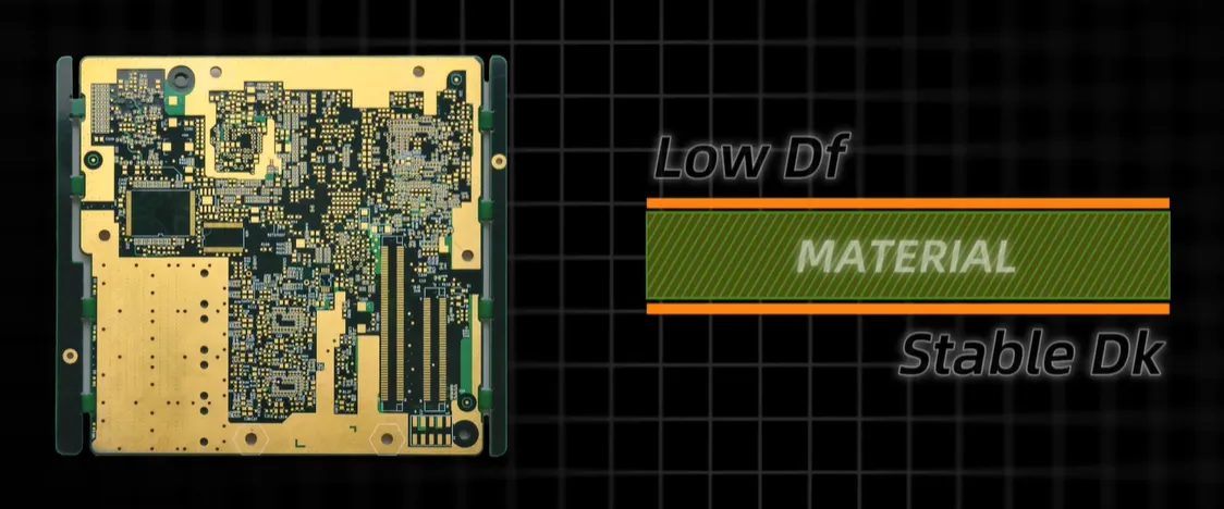
This video provides a detailed engineering overview of Rogers PCBs, high-performance laminates specifically engineered for RF and microwave circuits. It explains how low dielectric loss, stable Dk values, and excellent thermal management deliver minimal insertion loss, consistent impedance, and precise signal integrity even at gigahertz frequencies. Viewers learn why Rogers materials outperform standard FR4 in harsh environments by resisting high temperatures and maintaining dimensional stability.
Key applications highlighted include 5G base stations, satellite systems, automotive radar, and medical imaging equipment where RF precision and long-term reliability are essential. The video also covers our manufacturing support for multilayer RF/5G PCBs, high-frequency and high-speed designs, and other Rogers-based solutions. For instant pricing on your next project, use our PCB online quote tool. Full material specifications and stack-up guidelines are available on the Rogers PCB page.
Key Highlights
- Low dielectric loss and stable Dk values ensure minimal insertion loss and consistent impedance for reliable gigahertz-frequency performance.
- Superior thermal management and dimensional stability outperform FR4 in high-temperature and harsh operating conditions.
- Ideal for demanding RF applications including 5G base stations, automotive radar, satellite systems, and medical imaging equipment.
Core Material Properties That Enable Gigahertz Performance
Rogers laminates are formulated with ceramic-filled hydrocarbon or PTFE-based systems that achieve dissipation factors typically in the range of 0.001–0.004. This low loss characteristic directly reduces insertion loss on transmission lines operating above 1 GHz. Stable dielectric constant values across temperature and frequency minimize impedance variation, supporting tighter controlled-impedance designs without the Dk drift commonly observed in FR4.
Thermal conductivity is higher than standard epoxy-glass materials, allowing better heat spreading in high-power RF amplifiers and power dividers. Dimensional stability remains high under thermal cycling, limiting registration shift during multilayer lamination and subsequent assembly. These combined properties make Rogers materials suitable for circuits where phase stability and signal amplitude consistency are mandatory.
In production, the lower moisture absorption of most Rogers grades further protects high-frequency performance after reflow or in humid field environments. Designers must still account for the specific Dk and Df values published for each grade, as even small deviations affect modeled versus measured results at millimeter-wave frequencies.
Performance Differences Between Rogers PCB and Standard FR4
Standard FR4 exhibits rising dielectric loss and shifting Dk as frequency increases, leading to higher attenuation and impedance mismatch above a few gigahertz. Rogers materials maintain nearly constant electrical properties over wide frequency and temperature ranges, delivering lower loss and more predictable phase velocity.
Mechanical differences also appear during fabrication. Rogers laminates generally show lower z-axis expansion, improving plated-through-hole reliability under thermal stress. However, the ceramic fillers alter drill behavior and require adjusted process parameters compared with conventional FR4.
The following comparison summarizes typical property ranges relevant to RF design and manufacturing:
| Property | Typical Rogers (e.g., RO4350B class) | Standard FR4 | Manufacturing Impact |
|---|---|---|---|
| Dielectric Constant (Dk) | 3.0–3.5 | 4.2–4.8 | Tighter impedance control, reduced thickness variation sensitivity |
| Dissipation Factor (Df) | 0.002–0.004 | 0.015–0.025 | Lower insertion loss at GHz frequencies |
| Thermal Conductivity | Higher (approx. 0.6 W/m·K) | Lower (approx. 0.3 W/m·K) | Improved heat dissipation in power RF circuits |
| Moisture Absorption | <0.1 % | 0.1–0.3 % | Better long-term electrical stability |
| Z-axis CTE | Lower | Higher | Enhanced via reliability under thermal cycling |
Primary RF and Microwave Applications for Rogers Laminates
5G base-station antennas and filters rely on low-loss Rogers materials to maintain efficiency and beam-forming accuracy across wide bandwidths. Automotive radar modules operating at 77 GHz and higher require the dimensional and electrical stability that Rogers laminates provide under temperature extremes and vibration.
Satellite communication payloads and ground terminals use these materials for low-noise amplifiers and high-power amplifiers where every tenth of a decibel of loss affects link budget. Medical imaging systems, including certain MRI and microwave imaging components, benefit from the consistent dielectric behavior that supports precise signal timing and amplitude control.
In each case the material choice is driven by the need for predictable RF performance rather than lowest cost, making Rogers the preferred solution when FR4 would introduce unacceptable loss or instability.

Multilayer High-Frequency Fabrication Support
Multilayer Rogers constructions are routinely produced with mixed dielectric stack-ups, sequential lamination, and tightly controlled impedance structures. Fabrication capabilities include high-frequency and high-speed circuit manufacturing, advanced via structures, and thermal-management features optimized for RF reliability. Controlled-impedance routing, back-drilling, and laser-drilled microvias are supported when the design requires them.
Stack-up guidelines emphasize matching copper weights, core thicknesses, and prepreg types to the selected Rogers grade so that the finished board meets both electrical and mechanical targets. Full material data and recommended stack-up examples are provided on the dedicated Rogers PCB resource page.
Critical DFM Considerations During Rogers PCB Production
Successful Rogers PCB fabrication begins with accurate material selection and stack-up definition. Designers should specify the exact Rogers grade, copper foil type, and thickness early, because Dk and thickness tolerances directly influence impedance. Avoid mixing dissimilar materials within the same stack-up unless the CTE mismatch has been thoroughly modeled; otherwise registration and reliability problems appear after lamination.
Drill parameters must be adjusted for the ceramic content. Higher spindle speeds and specialized drill bits reduce smear and improve hole quality. Plasma or chemical desmear processes are often required to ensure reliable plating adhesion on the resin-rich surfaces. Copper surface preparation before oxide treatment or alternative adhesion promoters is critical to prevent delamination during subsequent thermal cycles.
Impedance coupons should be placed on every panel and measured after fabrication. Because Rogers materials exhibit lower loss, small geometric variations become more visible electrically; therefore etch-factor compensation and differential-etch control are essential. Solder-mask selection and application thickness also affect high-frequency performance and must be validated for the intended frequency band.
When these DFM rules are followed, first-pass yield improves and field failures related to via cracking or impedance drift are minimized.
Common Processing Risks and Failure Modes with Rogers Materials
One frequent risk is delamination caused by incorrect lamination pressure or temperature profiles. Rogers hydrocarbon-ceramic systems require specific cycle parameters; deviations produce voids or weak bonds that later open under thermal stress. Another common issue is plated-through-hole barrel cracking when the z-axis expansion of the laminate is not matched by the plating ductility or when drill quality leaves rough walls.
Excessive moisture entrapment before lamination or assembly can generate steam voids during reflow, particularly in thicker multilayer boards. Surface contamination or inadequate oxide treatment leads to poor copper-to-laminate adhesion and subsequent pad lifting. At millimeter-wave frequencies, even minor etch undercut or solder-mask thickness variation can shift impedance enough to degrade return loss.
Mitigation starts with process qualification for each Rogers grade, including microsection evaluation of vias, thermal-stress testing, and electrical verification of impedance and insertion loss. Designers can further reduce risk by avoiding extremely thin cores, specifying appropriate copper weights, and providing clear stack-up documentation that includes the exact material call-outs.
Material Grade Selection for Targeted RF Circuit Requirements
Different Rogers grades are optimized for specific frequency ranges, loss budgets, and mechanical needs. Lower-Dk PTFE-based materials suit the highest-frequency applications where minimal loss is mandatory, while ceramic-filled hydrocarbon grades offer a balance of processability, cost, and performance for many 5G and radar designs.
Selection criteria include the operating frequency, required dissipation factor, thermal conductivity needs, and compatibility with standard multilayer processing. Cost considerations also play a role; higher-performance grades command premiums that must be justified by the system-level requirements. Early consultation of the material datasheets and recommended design rules prevents later redesigns when the chosen grade proves incompatible with the intended fabrication process or electrical targets.
FAQ
Q1: How do Rogers materials improve signal integrity compared to FR4 at high frequencies?
A1: Rogers materials improve signal integrity by offering lower dielectric loss, more stable dielectric constant (Dk) values, and better thermal stability than standard FR4. These properties reduce insertion loss, maintain consistent impedance, and support accurate high-speed signal transmission at gigahertz frequencies.
Q2: What multilayer and high-frequency capabilities are available for Rogers PCB fabrication?
A2: Rogers PCB fabrication supports multilayer RF and microwave PCB designs, high-frequency and high-speed circuit manufacturing, controlled impedance structures, and advanced stack-up configurations optimized for RF performance and thermal reliability.
Q3: Which RF and microwave applications benefit most from Rogers PCB technology?
A3: Rogers PCB technology is widely used in RF and microwave applications such as 5G base stations, satellite communication systems, automotive radar modules, medical imaging equipment, and other high-frequency electronic systems requiring precise signal performance and long-term stability.
This is a Rogers PCB — a high-performance laminate designed for RF and microwave applications.
Rogers materials minimize insertion loss, reduce signal distortion, and deliver consistent impedance across complex designs.
Built with low dielectric loss, stable Dk values, and excellent thermal management, it ensures precise signal integrity even at gigahertz frequencies.
They also improve reliability under harsh conditions, resisting high temperatures and maintaining dimensional stability where standard FR4 falls short.
You'll find Rogers PCBs in 5G base stations, satellite systems, automotive radar, medical imaging, and any product where RF precision and durability are critical.
We support multilayer RF / 5G RF PCB, High-Frequency & High-Speed PCB, and other Rogers PCB solutions.
Feel free to explore specifications, datasheets, and stack-up guidelines on our platform whenever you need them.





