










PCB Rounded Corners: Stop Cracking with Radius
What This Video Covers
This short video explains why sharp 90° corners on a finished PCB frequently crack or chip during handling, depaneling, or assembly, and how a simple radius solves the problem. Instead of a sharp angle, designers specify a smooth radius (typically R0.5 mm to R5 mm) that spreads mechanical stress and dramatically lowers the chance of edge damage.
The video walks through practical starting values: R0.5–1.0 mm for compact boards, R1.0–2.0 mm for most consumer products, and R3.0–5.0 mm for larger industrial panels. It also stresses that bigger is not always better because the radius consumes board real estate. Most boards are profiled by CNC routing, so the chosen radius must stay within the factory's tool capability. After adding the radius, copper, traces, and components still need proper edge clearance—commonly 0.3–0.5 mm—always confirmed against the manufacturer's DFM rules.
These practices apply equally to standard FR4 PCB designs and more demanding applications such as industrial control PCB or consumer electronics PCB. Engineers can validate the final outline and obtain an immediate cost check through an instant PCB quote before committing to production.
Key Highlights
- Sharp 90° corners create stress concentration that leads to cracking or chipping; a smooth radius (R0.5–5 mm) redistributes the load and raises mechanical reliability.
- Typical radius guidelines: R0.5–1.0 mm (small boards), R1.0–2.0 mm (consumer), R3.0–5.0 mm (large industrial)—always balanced against available board space.
- After adding the radius, maintain 0.3–0.5 mm edge clearance to copper/traces/components and confirm the factory's CNC routing capability before finalizing the outline.
Stress Concentration at Sharp 90° PCB Corners
When a PCB outline contains a sharp internal or external 90° corner, mechanical loads—whether from panel depaneling, vibration, drop testing, or even normal handling—concentrate at a single point. FR4, the most common base material, has limited toughness in the through-thickness direction. The result is micro-cracks that start at the corner and can propagate into the board, damaging traces, vias, or copper planes.
In high-volume production the risk appears early: boards chip during routing or V-scoring, or later during automated optical inspection and packaging. Medical, automotive, and industrial control boards are especially sensitive because they must survive repeated mechanical stress over years of service. Adding a controlled radius converts the stress riser into a smooth curve, lowering peak stress by a factor of two or more in typical finite-element models.
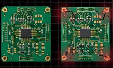
Factories routinely report higher scrap rates on panels that lack corner radii, especially when the outline includes deep internal corners or when the board is thin (0.8 mm or less). The fix is inexpensive at the design stage and almost free once the CNC program is written.
Recommended Corner Radius by Board Size and Application
| Board Category | Typical Size Range | Recommended Radius | Primary Reason | Notes / Trade-offs |
|---|---|---|---|---|
| Compact / wearable / IoT | < 50 × 50 mm | R0.5 – 1.0 mm | Minimal space loss, still reduces stress | Check component keep-out carefully |
| Consumer electronics | 50 – 150 mm | R1.0 – 2.0 mm | Balance of reliability and real estate | Most common production default |
| Industrial / power / control | > 150 mm or thick boards | R3.0 – 5.0 mm | Higher mechanical loads, larger tools | Confirm CNC tool diameter capability |
| Rigid-flex or thin flex | Any | R1.0 – 2.0 mm min | Prevents tearing at rigid-flex transition | Follow flex bend-radius rules as well |
These values are starting points only. Larger radii improve reliability but consume more copper area and can force redesign of edge connectors or mounting holes. Always run a quick space check in the CAD tool before locking the outline.
CNC Routing Limits and Edge Clearance Rules
Almost all production PCBs are shaped by CNC routers using carbide tools ranging from 0.8 mm to 2.0 mm diameter. The tool cannot physically create a perfect sharp internal corner; the smallest achievable internal radius is half the tool diameter. Specifying a radius smaller than the factory's standard tool forces a tool change, longer cycle time, and higher cost.
After the radius is added, every copper feature, trace, and component pad must maintain a minimum distance to the finished edge. Industry practice is 0.3–0.5 mm for outer layers on standard FR4; high-voltage or high-reliability designs often require more. Violating this clearance leads to copper burrs, exposed traces, or plating defects.
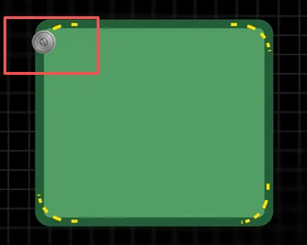
Before releasing the Gerber or ODB++ package, request the manufacturer's current routing capability list and DFM rules. Most reputable fabricators will flag an undersized radius or insufficient clearance automatically; resolving the issue at that stage is far cheaper than discovering cracked boards after assembly.
Practical DFM Checklist Before You Lock the Outline
- Replace every sharp 90° corner with a radius taken from the table above.
- Verify that the chosen radius is equal to or larger than half the factory's standard routing tool.
- Measure edge clearance to the nearest copper, pad, or component; adjust if below 0.3 mm.
- Confirm the outline still meets mechanical mounting and connector requirements.
- Include the radius value in the fabrication drawing notes so the CAM engineer does not miss it.
Following this short checklist eliminates the majority of corner-related yield losses and returns more usable boards from every panel.
FAQ
Q1: What corner radius should I specify for a typical 100 × 80 mm consumer PCB?
A1: R1.0–2.0 mm is the practical starting range. It reduces stress concentration without consuming excessive board area and matches the most common CNC tool diameters used in volume production.
Q2: Does adding a corner radius increase PCB fabrication cost?
A2: In almost all cases the cost impact is zero or negligible. The CNC program simply uses a different tool path. Cost only rises if the radius forces a non-standard tool or if the design violates edge-clearance rules and requires rework.
Q3: Can I use a very large radius (R5 mm or more) on every board to be safe?
A3: Not always. Oversized radii consume valuable real estate, can interfere with connectors or mounting holes, and may still be limited by the maximum tool size the factory runs. Match the radius to board size and mechanical load rather than defaulting to the largest possible value.
Q4: How does corner radius interact with V-scoring or tab-routing depaneling?
A4: A radius at external corners reduces the chance of the board cracking when the remaining tabs are broken. Internal corners that meet a V-score line should also receive a radius so stress does not concentrate at the intersection.
Q5: What edge clearance is required after adding the radius?
A5: 0.3–0.5 mm from the finished edge to the nearest copper feature is the common industry reference for standard FR4. Always confirm the exact value in the manufacturer's current DFM document, especially for high-voltage, impedance-controlled, or high-reliability designs.
You spent so much time designing your PCB, placed the order, and waited for it to arrive—only to find the board damaged. Could the problem be right here, at the corner?
Instead of a sharp 90° angle, you get a smooth radius like R0.5 mm, R1 mm or R2 mm.
It reduces stress concentration and lowers the risk of cracking or chipping.
Typical starting points: R0.5–1.0 mm for small boards, R1.0–2.0 mm for consumer products, and R3.0–5.0 mm for larger industrial boards. These are only guidelines — bigger isn't always better because it takes more space.
Most boards are shaped by CNC routing.
Once you add the radius, just make sure copper, traces and components still keep enough edge clearance. 0.3–0.5 mm is a common reference, but always follow your manufacturer's DFM.
Confirm the factory's routing capability before locking the outline.





