In the shop we set minimum internal corner radius according to the cutter we intend to use for the feature. For most 3-axis work this means at least 0.5 mm radius, preferably 1 mm or larger. CAM programmers select tool diameter first, then program the matching fillet. Sharp internal corners are only accepted when absolutely required and after we quote the additional operations needed.

How tool diameter directly dictates minimum CNC internal corner radius design
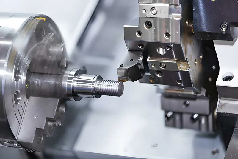
What we see daily in CAM is that specified zero-radius corners force us to use small diameter end mills even for large pockets. Small tools have limited rigidity and require reduced speeds and feeds. This increases cycle time dramatically and shortens tool life. A well-chosen CNC internal corner radius design lets us use larger, more stable cutters for roughing and leave minimal stock for finishing.
For aluminum parts we commonly run 6-8 mm tools with 1-2 mm radii. Steel needs slightly larger radii to manage heat and tool pressure.
Why sharp internal corners create real machining limitations
Sharp 90-degree internal corners stop the tool path abruptly. The cutter must decelerate, change direction, and accelerate again, causing vibration and poor surface finish at the corner. Tool deflection is highest exactly where accuracy matters most. In deeper features this leads to tapered walls or dimensional deviation.
Chip packing also becomes worse because there is no radius to help chips escape the corner. This is especially problematic in materials like stainless or titanium.

What happens in production when corner radii are too small or missing
Parts with undersized radii require slower feeds, more passes, and frequent tool replacement. We have seen cycle times double on otherwise simple components. Tool breakage risk goes up, leading to unplanned downtime and possible damage to the part. Surface finish at corners often fails inspection, requiring hand finishing or rework.
Overall job cost increases and delivery dates slip. In high volume runs these small design details can turn a profitable job into a loss.
Typical issues observed on the shop floor
- Chatter marks concentrated at internal corners
- Premature end mill failure
- Dimensional variation in pocket depth and width
- Difficult chip evacuation in blind pockets
- Higher programming and setup time
How factories select tool radius and apply corner design rules
During DFM we analyze the part geometry and recommend standard radii that match our most efficient tooling. We prefer the same radius value used throughout the part when possible to minimize tool changes. For functional sharp edges we isolate them and plan secondary processes rather than forcing the entire program around one difficult feature.
CAM toolpaths are optimized with these radii in mind, allowing constant tool engagement strategies that reduce load variation and improve tool life.

Practical ways CNC internal corner radius design reduces overall cost
Larger allowable radii let us use higher feeds and speeds, shortening cycle times. Fewer tool sizes simplify setup and reduce inventory costs. Better chip flow means less downtime for cleaning. Parts with good corner design also have lower stress concentrations, improving performance and reducing warranty issues downstream.
We often save 15-30% in machining time simply by adjusting a few radii during the quoting stage. These changes rarely affect the part function when reviewed with the designer.
When smaller radii or sharp corners can still be accepted
For prototypes or very low quantities we can machine smaller radii using dedicated small tools, but we note the cost premium. Certain mating features or sealing surfaces may legitimately require sharp corners. In those cases we clearly communicate the manufacturing impact and offer alternatives like EDM for those specific features only.
The key is early communication. A CNC internal corner radius design that works with production tooling keeps costs down and quality high without compromising the engineering intent.