In CNC low volume production design we treat every feature as a potential setup cost. Most shops running 5–50 pieces will reject or heavily markup any geometry that forces custom hard fixtures, special cutters, or more than two operations. The practical rule is simple: design the part so it can be held with soft jaws or a vise, cut with standard end mills and drills from the tool library, and finished in the fewest possible setups. Anything that violates that rule gets flagged during the first CAM review and either redesigned or quoted as high-cost.

Where Setup and Tooling Costs Dominate the Quote
Low-volume work has almost no amortization. A custom aluminum soft-jaw set still costs 2–4 hours of programming and machining. A specialty form tool or long-reach end mill that is not already in the carousel can add another day of ordering and another setup change. When the batch is only twenty pieces, those fixed costs land directly on the unit price. That is why shops push designers toward geometry that can be gripped on existing parallels or soft jaws and cut with ¼-inch, ⅜-inch, and ½-inch carbide end mills that are already loaded.
Material behavior also plays a role. Aluminum and mild steel leave the machine with residual stress after roughing; if the part has thin walls or large open pockets, it can move enough between operations to force a second alignment. In low volume there is no time to build stress-relief fixtures or run multiple stress-relief cycles, so the design itself has to keep wall thickness above 1.5 mm and avoid deep, unsupported pockets that distort after the first roughing pass.
What Happens When the Design Ignores Standard Workholding
The most common failure is a part that requires a five-axis setup or a dedicated fixture plate just to reach one undercut or side hole. That single feature can turn a two-operation job into a four-operation job. Each extra setup introduces alignment stack-up of 0.05–0.1 mm and another chance for operator error. In practice we see scrap rates climb from under 2 % to 8–12 % once the number of setups exceeds three on a low-volume run. Lead time stretches because the fixture itself has to be programmed, cut, and verified before the first part ever runs.
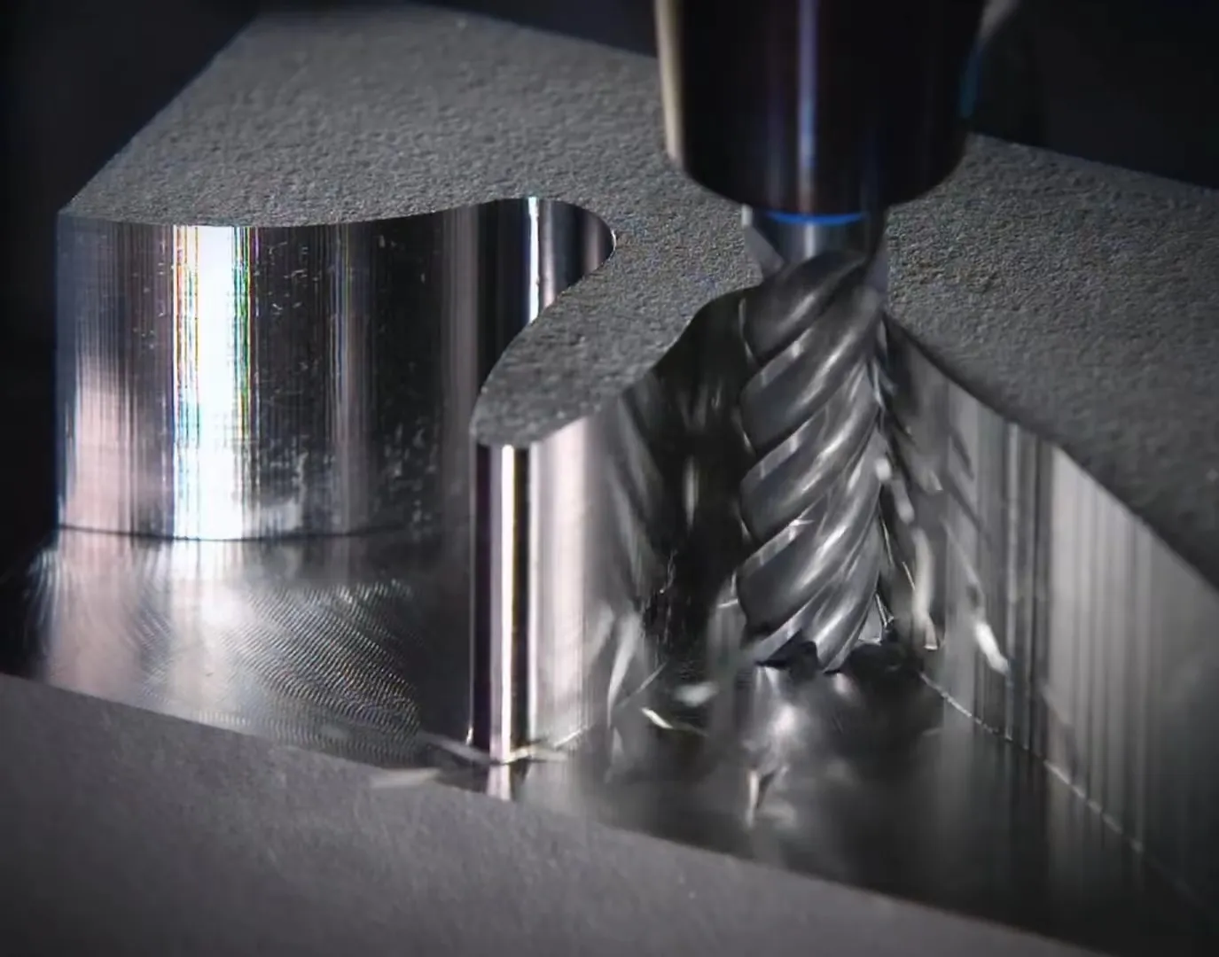
Tooling is the second killer. A design that needs a 1.2 mm ball-end mill for a cosmetic radius or a long-reach tool for a deep cavity forces the shop to buy or grind a special cutter. For a batch of ten parts the tool cost alone can exceed the material cost. If the tool breaks mid-run, the whole batch waits while a replacement is ordered. That is the daily reality when CNC low volume production design is not constrained to the standard tool list.

How Shops Actually Keep Low-Volume Jobs Economical
CAM engineers start by forcing every feature onto the standard tool library. Internal radii are pushed to 0.5 mm or larger so a standard 1 mm end mill can finish them. Pocket depths are limited so that a 3×D or 4×D length tool can reach without chatter. Any hole that is not a standard drill or reamer size is changed to the nearest available size or converted to a milled slot if the function allows. These changes are made in the first CAM pass and sent back as redlines before any metal is cut.
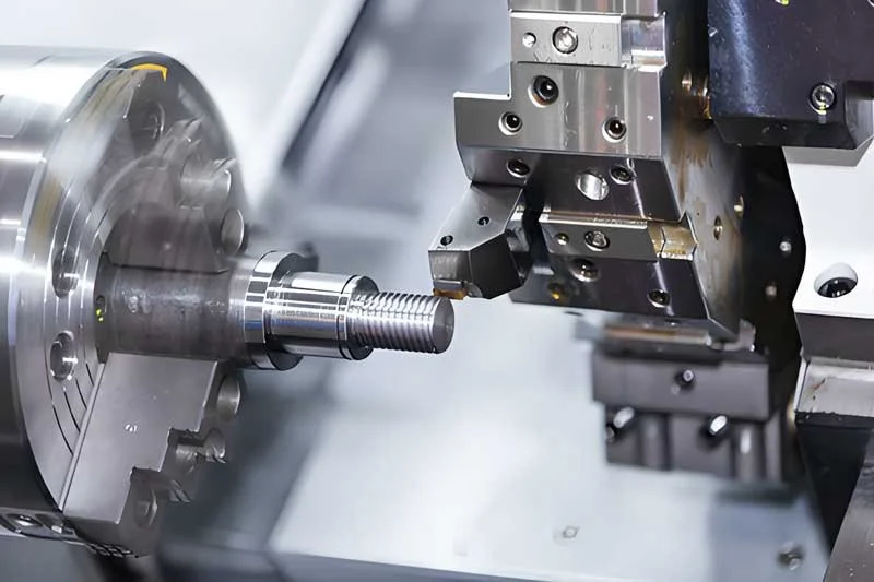
Workholding is simplified the same way. The preferred approach is to leave two parallel faces or a pair of locating edges that can sit against soft jaws or a vise. If the finished part has no such faces, the designer is asked to add temporary tabs or sacrificial stock that is machined away in the last operation. For prismatic parts we also leave a small amount of extra stock on the bottom so the part can be flipped and finished without losing the original datum. That single extra 0.5 mm of stock often eliminates an entire custom fixture.
Cycle time is controlled by reducing tool changes and air cuts. Features that can share the same tool diameter are grouped so the machine does not stop to change tools every few minutes. Deep pockets are roughed with a large-diameter tool first, then finished with a smaller tool only where needed. On a typical 3-axis mill this approach can cut cycle time by 30–40 % compared with a design that forces frequent tool swaps or long-reach finishing passes.

When the Shop Will Accept More Complex Geometry
Exceptions are granted when the functional requirement cannot be met any other way and the customer accepts the cost and lead-time impact. A sealed housing that must have an undercut O-ring groove, or a structural bracket that needs a thin wall for weight, will still be accepted, but the quote will carry a clear line item for the special fixture or 5-axis time. In those cases the shop usually asks for a second, simplified version of the same part that can be used for early prototypes while the complex version is reserved for final units. That way the low-volume production still starts with standard tooling and only moves to the expensive process once the design is frozen.
The practical limit is usually three setups and tools already present in the machine’s carousel. Beyond that point most shops will either refuse the job or price it as a prototype rather than true low-volume production. Designers who stay inside those limits keep the unit cost predictable and the delivery schedule short.