










Most HDI routing problems are already decided before the first microvia is placed. The schematic is finished, the stack-up is locked, and the parts go down. Then the autorouter or the manual fanout hits a wall. The channels that looked open on the schematic floorplan are blocked by a decoupling cap, a connector body, or another BGA sitting 0.3 mm too close.
HDI component placement is not just about fitting parts. It is about leaving controlled exit paths for microvias, stacked vias, and the short, clean routes that HDI is supposed to enable. Get the placement wrong and the density advantage disappears. Extra layers, longer traces, and compromised SI become the only remaining options.
BGA Placement That Closes Escape Channels Before Routing Starts
The most common mistake is treating a fine-pitch BGA like any other part. Pin-1 orientation is chosen for schematic convenience or silk-screen clarity. Distance to the next BGA or to a connector is set by the mechanical envelope only. No one measures the remaining channel width for the first two rows of escapes.
On a 0.4 mm or 0.35 mm pitch device the outer two rows need clear paths for microvias or dog-bone fanouts. When another large component sits closer than 1.5–2 mm, those paths collapse. The designer then forces vias under the BGA or adds extra layer transitions just to get the signals out. Both solutions cost density and add stubs.
Orientation matters more than most teams admit. Rotating a BGA 90° can turn a blocked differential pair into a straight microvia column. Leaving the part "as drawn" in the schematic often locks the worst orientation in place.
Decoupling Caps That Steal Fanout Real Estate
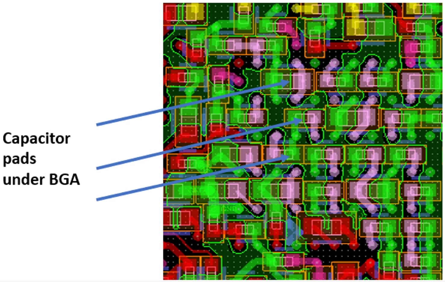
Power integrity wants the caps as close as possible to the power balls. HDI routing wants those same locations empty so microvias can drop straight down. The usual compromise—placing a cluster of 0402 or 0201 caps immediately outside the BGA outline—blocks the very channels the outer signal balls need.
The result is visible in almost every dense HDI review. The first row of signal escapes has to dog-leg around the capacitor pads or jump to a deeper layer earlier than planned. Via count rises. Crosstalk increases. The power plane under the BGA is also punctured more than necessary.
A better pattern is to reserve the immediate perimeter for signal fanout and place the highest-frequency caps in the open areas between BGA groups or on the opposite side of the board when the stack-up allows. Lower-frequency bulk caps can sit farther out. The placement decision has to be made while the BGA is still movable, not after the fanout is already committed.
Connectors That Force Unnecessary Layer Changes
High-speed connectors are often dropped at the board edge with only mechanical keep-outs considered. The high-speed lanes then have to snake past other components or drop through multiple HDI layers just to reach the connector pins.
In sequential-lamination HDI every extra layer transition adds a microvia or buried via. Registration, plating, and reliability all take a hit. If the connector had been rotated or shifted 3–4 mm earlier, many of those transitions could have been avoided. The signals could have stayed on the outer HDI layers for the entire run.
The same issue appears with board-to-board connectors placed between two dense BGAs. The corridor between the BGAs becomes the only path; the connector body and its mounting hardware close it. Routing density collapses and the designer is forced into longer, more complex routes.
Insufficient Fanout Space and the Cascading Congestion It Creates
Once the large parts are fixed, the remaining real estate is usually filled with smaller passives and local regulators. The gaps that should have been reserved as routing highways disappear. What looked like adequate channel width on the placement drawing becomes a series of bottlenecks once the actual pad and via keep-outs are applied.
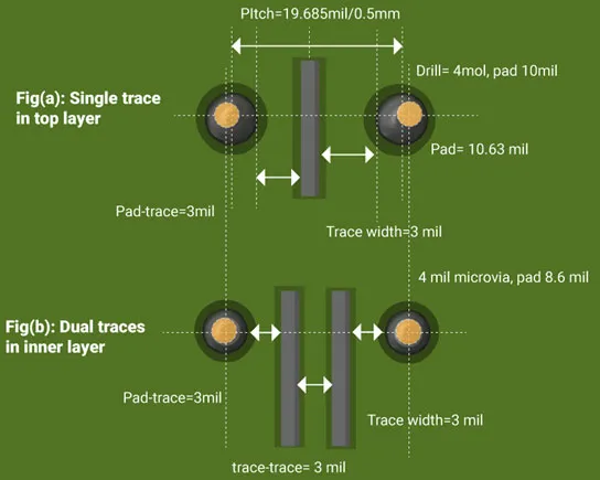
In HDI the problem is amplified. Microvia pads are larger relative to the trace width than traditional through-hole vias. A channel that could accept two 50 µm traces and a 100 µm via in a conventional design may accept only one trace after HDI pad sizes and annular-ring requirements are observed. Placement that ignores this difference guarantees congestion.
The congestion then forces additional vias, longer routes, and more layer changes. Signal integrity suffers. Manufacturing yield drops because clearances are pushed to the process limit. The original goal of HDI—shorter interconnects and higher density—is partially lost.
Placement Adjustments That Actually Free Routing Space
Fix the large components first while the board is still flexible. Measure the required escape width for every high-pin-count device, including the microvia pad size and the minimum residual annular ring. Add that width as a hard keep-out between parts. Do not rely on the mechanical outline alone.
Place the critical decoupling caps after the BGA fanout channels are defined, not before. If the highest-frequency caps must sit next to the power balls, use the opposite side of the board or the open areas inside a sparse BGA when the pinout allows. Never let a capacitor pad sit directly in a signal escape path.
Orient connectors so the high-speed lanes have a straight shot to the outer HDI layers. Shift them a few millimeters if that eliminates even one layer transition. The mechanical drawing can usually absorb small movements; the routing cannot.
After the major parts are locked, leave explicit routing corridors between component groups. These corridors should be wide enough for the planned trace/via combination plus manufacturing tolerance. Treat them as placement features, not leftover space.
HDI component placement succeeds or fails on the same principle as the rest of the technology: leave the copper and the dielectric the room they need to do their jobs. When placement decisions ignore fanout space, registration realities, and the size of microvia pads, routing becomes an exercise in damage control. When those same decisions reserve the necessary channels from the start, the routing finishes cleaner, shorter, and more reliable.






