Many PCB designs fail at the assembly stage not because of layout errors, but because the pick-and-place data is incomplete, rotated incorrectly, or misaligned with the Gerbers. Automated SMT lines rely on precise placement coordinates and rotation angles. Without clean centroid data, machines cannot place components accurately, leading to polarity reversals, missing parts, or costly rework.
This guide explains how to generate reliable pick-and-place (also called position, centroid, or CPL) files in KiCad, what the data actually means, how to prepare it for manufacturers, and how common mistakes affect real SMT production. You will walk through the complete workflow from board origin setup to verified manufacturing files ready for assembly.
What is a Pick-and-Place File?
A pick-and-place file is a machine-readable list that tells the SMT equipment the exact location, rotation, and side of every surface-mount component on the bare PCB.
It is also known as a centroid file, XY file, position file, PnP file, or CPL (Component Placement List). In KiCad it is officially called the Component Placement File and normally carries a .pos extension (or CSV when that format is selected).
The file does not contain electrical connectivity or pad geometry. It only supplies the geometric data the placement machine needs: where to pick the part from the feeder and how to orient it before placing it on the solder paste.
Why SMT Manufacturers Need Placement Data
Modern pick-and-place machines operate at high speed and high accuracy. They use optical systems and the placement file to:
- Locate the board using fiducials or the defined origin
- Move the nozzle to the correct X/Y coordinate
- Rotate the component to the required angle
- Decide whether the part belongs on the top or bottom side
Without this data, the manufacturer must either program the machine manually (slow and error-prone) or reject the job. Even a small coordinate offset or 90° rotation error can cause an entire batch of boards to be assembled incorrectly.
From a manufacturing perspective, clean pick-and-place data is as critical as correct Gerbers and a complete BOM. It is the bridge between your KiCad layout and the physical assembly process.
Understanding Pick-and-Place File Contents
KiCad exports a consistent set of fields. Understanding each column prevents most downstream problems.
Component Reference
The reference designator (R1, C12, U3, etc.). This must match the designators in the schematic, BOM, and silkscreen. Manufacturers use it to cross-check quantities and polarity.
X/Y Coordinates
The position of the component's placement origin (normally the geometric center of the footprint) relative to the drill/place file origin you set in the board. Units are almost always millimeters for modern SMT equipment. Coordinates must be consistent with the Gerber origin; otherwise the entire placement is shifted.
Rotation Angle
The angle in degrees that the machine must rotate the part from its zero-orientation state. KiCad reports the rotation as defined in the footprint library and the board placement. There is no universal agreement between CAD tools, tape orientation, and machine software on what "0°" means, so manufacturers frequently apply a fixed offset for certain packages.
Layer Information
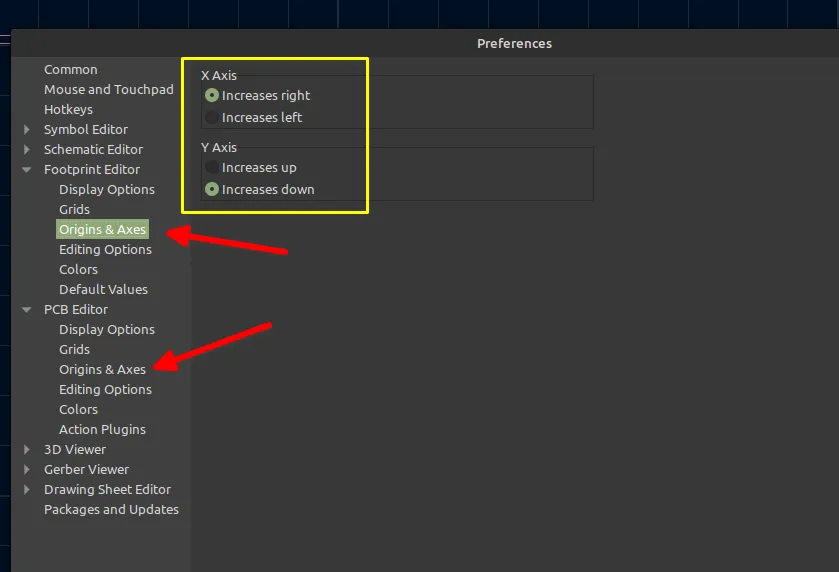
Top or bottom (front or back). Some formats use "top/bottom", others use "1/2" or "T/B". Bottom-side components are often mirrored in the coordinate system; KiCad provides an option to negate the X coordinate for the bottom side to match certain machine conventions.
Generating Position Files in KiCad
Export Workflow
- Open the finished board in the PCB Editor.
- Set a consistent origin: Place → Drill/Place File Origin. Place it at the lower-left corner of the board outline (or the same point used for Gerbers and drills).
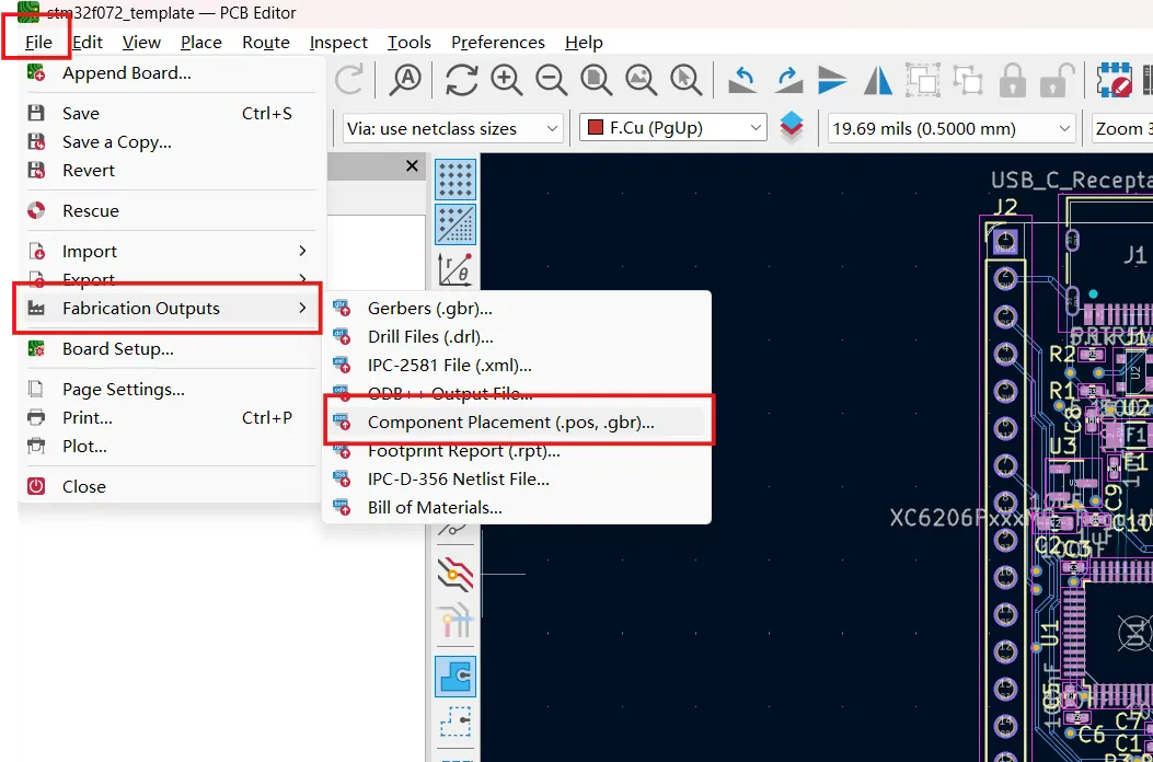
- Go to File → Fabrication Outputs → Component Placement (.pos, .gbr)… (wording may vary slightly between KiCad 8/9/10).
- In the Generate Placement Files dialog:
- Choose the output directory.
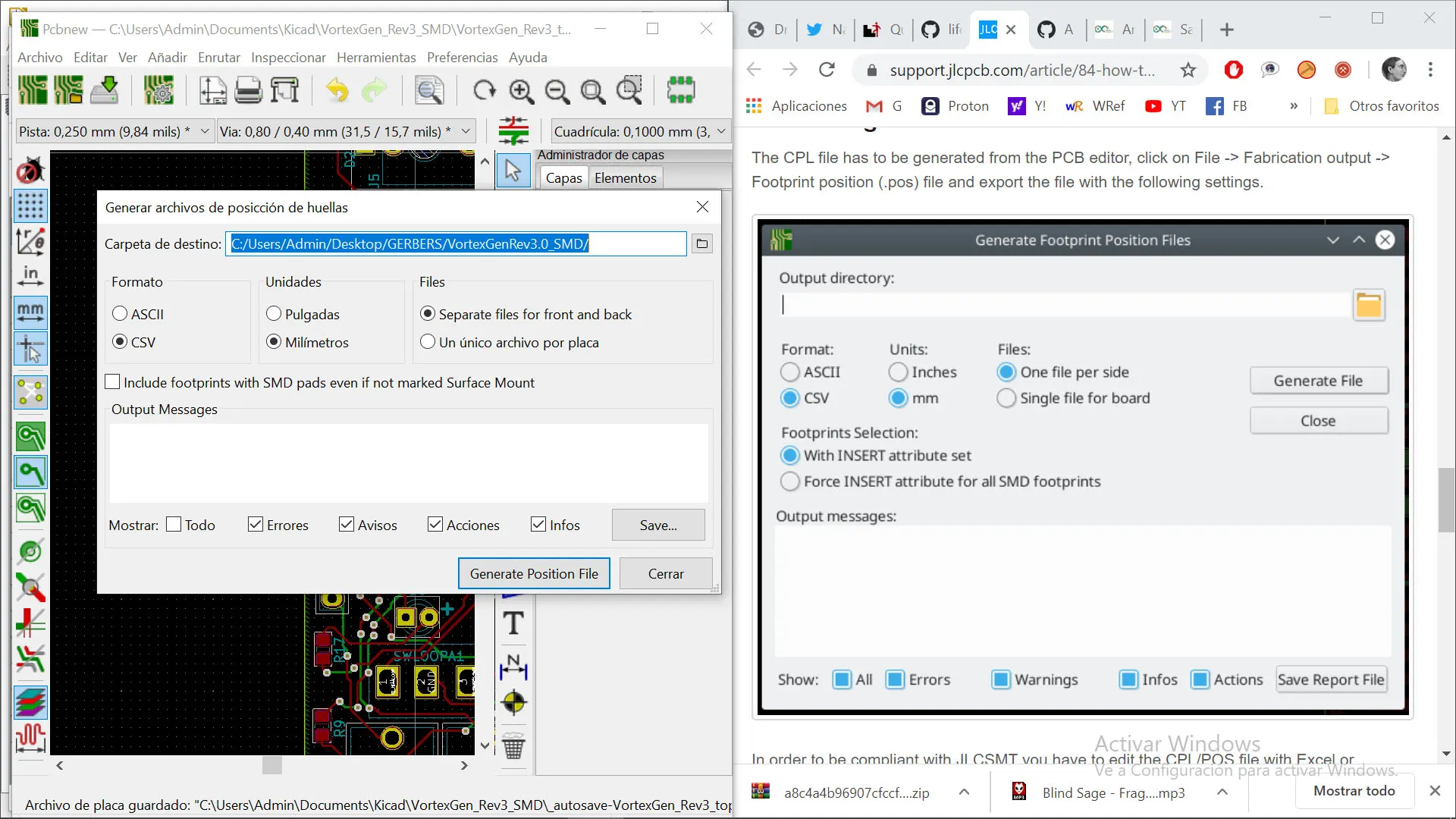
- Select format (CSV is preferred by most assembly houses; ASCII/plain text is also widely accepted).
- Set units to millimeters.
- Choose single file or separate files for front and back.
- Enable "Use drill/place file origin".
- Optionally restrict to SMD footprints only and exclude DNP parts.
- Click Generate Position File and check the Output Messages window for success.
The resulting file(s) contain every included footprint with its reference, value, package, coordinates, rotation, and side.
Configuration Options
- Format: CSV for spreadsheet editing and manufacturer portals; ASCII for simple text parsers.
- Units: Always millimeters unless the manufacturer explicitly requests inches.
- Files: Separate top/bottom files avoid confusion on double-sided boards.
- SMD only / Exclude through-hole / Exclude DNP: Use these filters so the file contains only parts the pick-and-place machine will actually place.
- Bottom-side X negation: Enable if your manufacturer's software expects mirrored coordinates for the bottom side.
- Gerber format: Rarely used for traditional PnP machines; mainly for certain advanced systems.
Always generate the position file after the final DRC and after the Gerbers so that the origin and any last-minute footprint moves are captured.
Preparing Pick-and-Place Data for Assembly
Verify Component Orientation
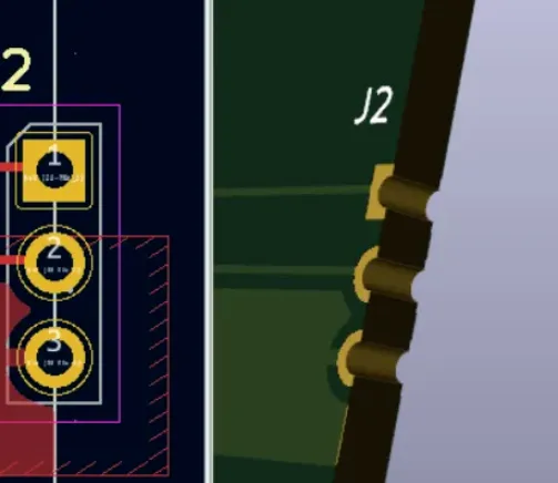
Open the generated file and compare a few critical parts (ICs, polarized capacitors, diodes, connectors) against the PCB layout and the 3D view. Confirm that pin 1 or the polarity mark matches the intended orientation. Remember that the rotation value in the file describes the part on the board, not its orientation inside the tape or reel. Manufacturers normally correct for tape orientation during programming.
Check Placement Accuracy
- Confirm the origin matches the Gerber and drill origin.
- Spot-check several coordinates by measuring in the PCB Editor.
- Ensure no components marked "Exclude from position files" appear in the list.
- For double-sided boards, verify that top and bottom parts are correctly assigned.
- If the manufacturer requires specific column headers (e.g., Designator, Mid X, Mid Y, Rotation, Layer), rename the KiCad headers in a spreadsheet before uploading.
A quick visual cross-check between the position file, the silkscreen, and an assembly drawing catches most errors before the boards reach the line.
Common Pick-and-Place Issues
Incorrect Rotation
The most frequent cause of polarity failures. Root causes include:
- Footprint library zero-orientation different from the manufacturer's expectation
- Bottom-side components not mirrored consistently
- Manual editing of the rotation column without understanding the machine convention
Result: ICs or polarized parts placed 90° or 180° out of position. Fix by verifying critical footprints in the library and letting the manufacturer apply a global offset if needed.
Missing Components
Components disappear from the file when:
- The footprint is not marked as SMD
- "Exclude from position files" is checked
- The export filter excludes through-hole or DNP parts
- The footprint has no valid placement origin
Always review the output message list and compare the number of lines against the expected SMD count from the BOM.
Coordinate Mismatch
Usually caused by:
- Different origins used for Gerbers versus the position file
- Units mixed (mm vs inches)
- Board outline moved after the origin was set
This shifts every component by a constant offset and is immediately visible when the manufacturer overlays the placement data on the Gerber.
Working with PCB Assembly Manufacturers
After you have clean Gerbers, drill files, BOM, and pick-and-place data, the next step is submitting the package for fabrication and assembly.
Most manufacturers accept the KiCad .pos or CSV format directly, provided units are millimeters and the origin is consistent. Some portals require header renaming or a combined top/bottom file; others accept the native KiCad output without changes. Always check the manufacturer's documentation for the exact column order and whether they prefer separate side files.
When the design is complete, engineers can export the full manufacturing package (Gerbers, drills, BOM, and pick-and-place) and submit it for quotation and production. After completing the KiCad design process, engineers can export manufacturing files and submit them to AIVON for PCB fabrication and assembly. AIVON accepts standard pick-and-place formats (.pos, CSV, TXT) with X/Y coordinates, rotation, and designators in millimeters, and provides both fabrication and turnkey assembly services. Their KiCad-related workflow tools further simplify packaging the necessary files for ordering.
Before final submission, run a quick DFM review of the placement data against the board outline and fiducials. This last check significantly reduces the chance of assembly holds or respins.
FAQ
Q1: What is the difference between a pick-and-place file and a centroid file in KiCad?
A1: They are the same data. "Pick-and-place," "centroid," "XY," "position," and "CPL" all refer to the component placement file that KiCad generates under Fabrication Outputs. The only practical difference is the file format (CSV vs ASCII) and the exact column headers preferred by a given manufacturer.
Q2: Why are some of my SMD components missing from the KiCad position file?
A2: The most common reasons are that the footprint is not attributed as Surface Mount, the "Exclude from position files" option is enabled on the footprint, or the export dialog is set to include only certain attributes. Open the footprint properties, confirm the fabrication attributes, and re-export with the SMD filter enabled.
Q3: Do I need separate pick-and-place files for top and bottom sides?
A3: Many manufacturers accept a single combined file that includes a Side or Layer column. Others prefer two separate files. KiCad can generate either. When in doubt, generate separate files and ask the assembler which format they prefer; it is easier to combine later than to split.
Q4: How do I make the coordinates match my Gerber origin?
A4: Always set the Drill/Place File Origin in the PCB Editor to the same reference point used for Gerber and drill export (normally the lower-left corner of the board outline). Enable "Use drill/place file origin" in the position-file dialog. This single step eliminates most coordinate-mismatch problems.
Q5: Can I edit the rotation values in the pick-and-place file myself?
A5: It is better to correct the footprint orientation or placement in KiCad and re-export. Manual edits can introduce inconsistencies with the silkscreen and 3D model. If a global offset is required for a particular package family, document it clearly for the manufacturer rather than changing individual lines.