5G-Advanced (5G-A) marks the first major evolutionary step beyond initial 5G deployments, with 2024 widely recognized as its launch year. Among the earliest and most impactful technologies is three-component carrier aggregation (3CC), which combines three frequency bands to deliver substantially higher data rates than single-carrier or dual-carrier configurations.
Understanding 3CC Carrier Aggregation
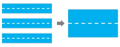
3CC refers to the aggregation of three component carriers (CCs) to create a wider effective bandwidth. In wireless systems, each carrier occupies a specific radio frequency band. By combining three carriers, operators achieve higher peak throughput while maintaining compatibility with existing spectrum allocations.
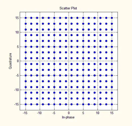
Carrier aggregation itself originated in LTE-Advanced to meet 4G performance targets. In 5G, it serves the same purpose: overcoming the practical limits of modulation schemes and individual band widths. With millimeter-wave spectrum seeing limited deployment and the 6 GHz band not yet widely available, efficient use of sub-6 GHz spectrum through aggregation becomes the primary path to multi-gigabit speeds.
Carrier Aggregation Types and Component Carrier Roles
3GPP defines three main carrier aggregation configurations:
- Intra-band contiguous CA
- Intra-band non-contiguous CA
- Inter-band non-contiguous CA
Each participating carrier is a component carrier. One carrier functions as the primary cell (PCell), handling control signaling and mobility management. Additional carriers act as secondary cells (SCells) that dynamically expand bandwidth and throughput.
3CC Deployments and Spectrum Combinations
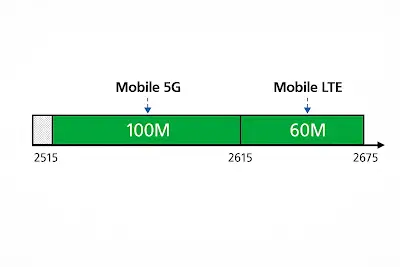
Chinese operators have pioneered early 3CC rollouts using specific band combinations. China Mobile has demonstrated 700 MHz (30 MHz) + 2.6 GHz (100 MHz) + 4.9 GHz (100 MHz), totaling 230 MHz, with potential expansion to 260 MHz. China Telecom and China Unicom commonly use 2.1 GHz (40 MHz) + 3.5 GHz (200 MHz), sometimes supplemented by 900 MHz spectrum.
Field measurements frequently exceed 4 Gbps downlink, with select tests surpassing 5 Gbps when combined with 1024QAM. Uplink performance benefits from supplemental uplink (SUL) techniques, reaching several hundred Mbps and occasionally exceeding 1 Gbps under favorable conditions. 3CC supports mixed FDD+TDD aggregation and benefits from 3GPP Release 18 features such as Flexible Spectrum Access (FSA) and Multi-Band Serving Cell (MB-SC), which optimize resource scheduling across bands.
Key Applications and Performance Benefits
3CC primarily increases achievable data rates from sub-1 Gbps to 3–5 Gbps in ideal conditions, making sustained user-experience speeds above 1 Gbps practical even in loaded networks. This capability supports bandwidth-intensive services including live 4K/8K streaming, cloud gaming, autostereoscopic 3D, and extended reality (XR/VR) applications.
High-density venues such as airports, stadiums, and urban transit hubs represent prime deployment targets. In industrial settings, 3CC enables smart manufacturing, AI-based visual inspection, remote operations, and high-definition surveillance by providing the necessary uplink and downlink capacity for multiple high-rate devices. Fixed wireless access (FWA) also benefits, delivering broadband-like performance to customer premises equipment (CPE).
Device and Modem Requirements
Support for 3CC depends on the modem chipset. Qualcomm X75 and MediaTek M80 modems theoretically enable 3CC in 5G NR FR1 (up to 300 MHz) with peak rates approaching 5 Gbps downlink. Reported compatible smartphones include Honor Magic6 Pro, Xiaomi 14 Pro, vivo X100 Pro, and OPPO Find X7. Current iPhone models do not support 3CC.
PCB Design and Manufacturing Considerations for 3CC-Enabled Devices
Achieving reliable 3CC performance imposes strict requirements on 5G PCB design and fabrication. Multi-band RF front-ends demand low-loss, high-frequency laminates with stable dielectric constants across the aggregated spectrum. Material selection must balance insertion loss, thermal stability, and cost while supporting the simultaneous operation of widely spaced bands (e.g., 700 MHz to 4.9 GHz).
High-density interconnect (HDI) technology and precise impedance control become essential to maintain signal integrity across primary and secondary carriers. Antenna integration, often involving multiple MIMO elements, requires careful layout to minimize coupling and ensure consistent performance under varying load conditions. Thermal management is critical because higher data rates increase power dissipation in both the modem and RF power amplifiers.
From a manufacturing perspective, tight tolerances in copper thickness, dielectric uniformity, and via placement are necessary to achieve repeatable RF performance at scale. Reliability testing must encompass temperature cycling, humidity exposure, and mechanical stress to ensure long-term stability in mobile and industrial environments. Advanced surface finishes and controlled impedance routing further support the high-speed interfaces required by 3CC modems.
Industry Trends and Outlook
As 5G-A networks expand, 3CC is expected to serve as a bridge technology until broader 6 GHz and millimeter-wave adoption occurs. Continued evolution of Release 18 and future releases will introduce additional aggregation and spectrum-sharing mechanisms. Device ecosystems are gradually expanding, and operators are prioritizing deployments in high-traffic locations and vertical industries.
Supporting 5G-A Performance Through Advanced PCB Technologies
High-performance 5G-A devices and infrastructure rely on sophisticated PCB fabrication and assembly capabilities. Multi-layer PCBs using specialized low-loss materials, precise HDI stack-ups, and integrated thermal solutions directly enable the bandwidth aggregation and signal integrity demanded by 3CC. Flexible printed circuits (FPCs) further support compact antenna modules and dynamic form factors in modern handsets and industrial equipment. These manufacturing processes ensure that the theoretical speed gains of 3CC translate into consistent, real-world performance across diverse operating conditions.
FAQs
Q1: What is the practical speed improvement from 3CC?
A1: In ideal conditions, downlink speeds commonly reach 3–5 Gbps, with sustained user-experience rates above 1 Gbps feasible even in congested environments.
Q2: Which modems support 3CC today?
A2: Qualcomm X75 and MediaTek M80 chipsets provide theoretical support; several flagship Android smartphones have already demonstrated compatibility.
Q3: How does PCB material choice affect 3CC performance?
A3: Low-loss laminates with stable dielectric properties across multiple bands are essential to minimize insertion loss and maintain signal integrity when aggregating widely spaced carriers.