When designing systems with multiple DDR memory devices, the interconnect topology becomes a primary design decision that directly affects signal integrity, timing closure, and layout complexity. This article explains the key DDR topologies used in practice, their advantages and limitations, and typical application scenarios, with guidance on when each approach is appropriate.
Point-to-Point Topology
With a single DDR device, a point-to-point connection between the memory controller and the DRAM provides the simplest and most robust structure. A single transmission line segment with one driver and one load minimizes impedance discontinuities and reflection paths, making impedance control straightforward. Timing is also easier to manage because there are no intermediate branches or multiple devices to align. For high-speed bidirectional interfaces, point-to-point is the preferred choice whenever the design and capacity requirements allow it.
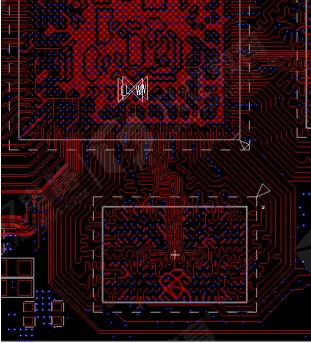
Figure 1 | Point-to-point DDR topology
Fly-by (Daisy-Chain) Topology
When multiple DDR devices are required, the fly-by (daisy-chain) topology connects the controller to each DRAM sequentially along a primary routing path. The command, address, and clock lines propagate past each device in order, with each device tapping into the main line via a very short branch. Among multi-load interconnects, the fly-by layout typically provides the most controlled impedance environment and the least susceptibility to high-order harmonic interference because it avoids long stubs and keeps the transmission line continuous.
In practical routing, keep every branch (stub) as short as possible. A useful guideline is to limit each branch's propagation delay to less than one-tenth of the signal's rise time. Short stubs mitigate resonances and reduce reflections that would otherwise degrade signal quality and close the eye. Because the main path remains continuous and stubs are minimized, the overall impedance profile is easier to control, making fly-by well-suited for high-speed signals and multi-device DDR channels.
One important tradeoff is skew. In a fly-by topology, loads are physically at different distances from the controller; the clock, address, and control signals arrive at each device at different times rather than simultaneously. To compensate for this flight-time difference, the controller and DRAM must support timing calibration techniques such as write leveling and read leveling. These mechanisms adjust internal delay elements to align data sampling in the presence of fly-by propagation delay. If the controller does not support such timing compensation, fly-by is not an appropriate choice.
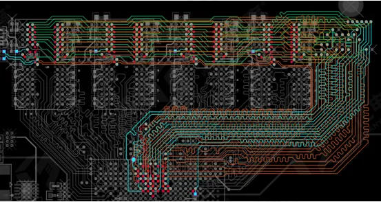
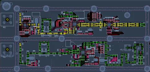
Figure 2 | Fly-by routing concept with short branch stubs
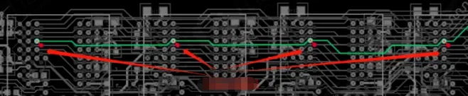
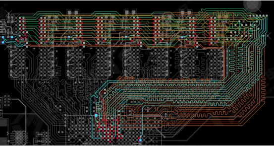
Figure 3 | Example of a fly-by topology implementation
T-Branch (Star/Tree) Topology
The T-branch topology—also referred to as star or tree—splits the interconnect into two or more branches at a T junction. Depending on where the split occurs relative to the driver and loads, two common variants are used: T near the driver and T near the loads.
T Near the Driver
When the T junction is placed close to the driver, the two branches originate near the controller and run outward toward the loads. This arrangement can alleviate clock synchronization concerns because each branch can be kept similar in length, making skew control more manageable. The branch lengths are also easier to constrain and balance, which can be useful when the driver has sufficient strength to feed multiple branches effectively. In this configuration, the main trunk between the controller and the split should be as short as possible to minimize the effect of the T junction on signal integrity.
The primary disadvantages are increased routing complexity and termination requirements. Each branch creates an impedance discontinuity that must be managed. Typically, termination resistors are required on the branches, and their values should match the characteristic impedance of the corresponding transmission lines. Without proper termination, reflections at the T junction and along the branches can severely distort the waveform and reduce timing margin.
T Near the Loads
When the T junction is closer to the loads, the main trunk runs toward the far end of the bus and splits near the devices. This approach balances the branches more naturally and is often used when many loads must be connected. In this case, termination can sometimes be consolidated: a single termination resistor placed appropriately may be sufficient, depending on the specific interconnect and device requirements. This makes the T-near-load configuration a common choice when a T topology is necessary.
Length management remains crucial. The relative lengths of the main line and its branches must be controlled to keep skew within acceptable bounds. A practical guideline in this configuration is to keep each branch length less than or equal to one-third of the main trunk length. Adhering to this constraint helps maintain a balanced impedance profile and limits reflection-induced ringing.
Practical Layout Notes
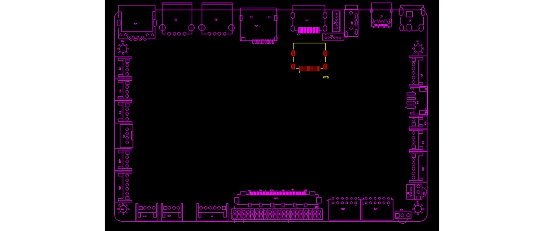
DDR components can be arranged in many ways on the PCB, including mirrored placement, staggered layouts, or single-sided groupings. Regardless of placement, the interconnects generally fall into the topologies described above: point-to-point, fly-by, or T-branch. The choice among them determines how you manage impedance control, reflection, routing difficulty, and timing alignment across the devices.
Topology Selection for DDR3, DDR4, and DDR5
For high-speed DDR generations such as DDR3, DDR4, and DDR5, the fly-by topology is often the preferred choice for the command, address, and clock networks. Compared with T-branch structures, fly-by significantly reduces stub-induced reflections because the branches are intentionally kept very short and the main interconnect is continuous. This topology naturally supports higher data rates with better signal integrity, provided timing calibration is available.
The inherent downside of fly-by—non-simultaneous signal arrival across devices—is addressed by timing compensation techniques. DDR3 introduced internal time compensation, commonly implemented through write leveling and read leveling. These features adjust internal delay elements to align the data and strobe capture window with the propagated clock and command/address signals at each device. Empirical results from simulation and practice consistently show that fly-by topologies handle higher speeds more reliably and improve the overall signal integrity of the bus when used with proper timing calibration.
Design Checklist and Guidelines
- Match the topology to device support: Use fly-by only if the controller and DRAM support read/write leveling and related timing calibration features. Without calibration, propagation delays in fly-by can cause excessive skew.
- Control branch stubs: In fly-by and T-branch layouts, keep each branch's effective electrical length short. A practical target is to ensure the branch's propagation delay is less than one-tenth of the signal rise time.
- Manage the T junction wisely: If using T near the driver, minimize the main trunk before the split and ensure the driver can support the branch load. If using T near the loads, balance branch lengths and adhere to the guideline that each branch should be less than or equal to one-third of the main trunk.
- Plan termination deliberately: Provide termination that matches the line impedance. In T near the driver, separate termination on each branch is typically required. In T near the loads, a single termination may be viable depending on the specific interconnect and device requirements. In all cases, ensure the termination strategy aligns with the topology and device features.
- Preserve a continuous reference: Maintain a continuous return path under all high-speed routes. Avoid splits and gaps in the reference plane that would introduce additional discontinuities and coupling.
- Route with consistent impedance: Keep trace width, spacing, and dielectric conditions consistent along the entire signal path. Avoid abrupt changes that would create impedance discontinuities and reflections.
- Control skew across devices: In fly-by, order the devices and route lengths to produce a monotonic, predictable delay chain. In T-branch, carefully match branch lengths to control skew between devices.
- Consider layout complexity: Fly-by typically eases impedance control but may constrain component placement to maintain a clear routing path. T-branch can offer placement flexibility at the expense of greater routing difficulty and more complex termination.
By selecting an appropriate topology and rigorously controlling impedance, branch lengths, and timing calibration, designers can achieve robust signal integrity and timing margin in multi-device DDR channels. For modern high-speed DDR interfaces, fly-by is generally the favored topology due to its reduced reflection risk and compatibility with built-in timing compensation. When design constraints necessitate a T-branch, careful management of branch lengths, termination, and driver capability can still deliver a compliant and reliable bus.